The 6 signals of the load connector are interpreted as the x-, y- and z-coordinates of a force and as the x-, y-, and z-coordinates of a torque acting at the frame connector to which frame_b of this component is attached. If connector frame_resolve is not connected, the force and torque coordinates are with respect to frame_b. If connector frame_resolve is connected, the force and torque coordinates are with respect to frame_resolve. In this case the force and torque in connector frame_resolve are set to zero, i.e., this connector is solely used to provide the information of the coordinate system, in which the force/torque coordinates are defined. The input signals are mapped to the force and torque in the following way:
   force  = load[1:3]
   torque = load[4:6]
Additionally, a force and torque acts on frame_a in such a way that the force and torque balance between frame_a and frame_b is fulfilled.
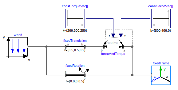
An example how to use this model is given in the following figure:
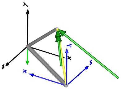
This leads to the following animation (the yellow cylinder characterizes the line between frame_a and frame_b of the ForceAndTorque component, i.e., the force and torque acts with negative sign also on the opposite side of this cylinder, but for clarity this is not shown in the animation):