The 6 signals of the load connector are interpreted as the x-, y- and z-coordinates of a force and as the x-, y-, and z-coordinates of a torque acting at the frame connector to which this component is attached. If connector frame_resolve is not connected, the force and torque coordinates are with respect to frame_b. If connector frame_resolve is connected, the force and torque coordinates are with respect to frame_resolve. In this case the force and torque in connector frame_resolve are set to zero, i.e., this connector is solely used to provide the information of the coordinate system, in which the force coordinates are defined. The input signals are mapped to the force and torque in the following way:
   force  = load[1:3]
   torque = load[4:6]
The force and torque are by default visualized as an arrow (force) and as a double arrow (torque) acting at the connector to which they are connected. The diameters and colors of the arrows are fixed and can be defined via parameters forceDiameter, torqueDiameter, forceColor and torqueColor. The arrows point in the directions defined by the inPort.signal signals. The lengths of the arrows are proportional to the length of the force and torque vectors, respectively, using parameters N_to_m and Nm_to_m as scaling factors. For example, if N_to_m = 100 N/m, then a force of 350 N is displayed as an arrow of length 3.5 m.
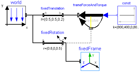
An example how to use this model is given in the following figure:
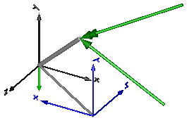
This leads to the following animation