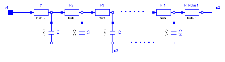
As can be seen in the picture below, the lossy RC line ULine is
a single conductor lossy transmission line which consists of
segments of lumped series resistors and capacitors that are
connected with the reference pin p3. The precision of the model
depends on the number N of lumped segments.
To get a symmetric line model, the first resistor is cut into two
parts (R1 and R_Nplus1). These two new resistors have the half of
the resistance of the original resistor.
The capacitances are calculated with: C=c*length/N.
The resistances are calculated with: R=r*length/(N+1).
For all capacitors and resistors the values of each segment are the
same except for the first and last resistor, that only has the half
of the above calculated value.
The user has the possibility to enable a conditional heatport. If so, the ULine can be connected to a thermal network. When the parameter alpha is set to an value greater than zero, the ULine becomes temperature sensitive
due to their resistors which resistances are calculated by
R_actual= R*(1 + alpha*(heatPort.T - T_ref)).
Note, this is different compared with the lumped line model of SPICE.
References