DC to DC converters
General information about DC/DC converters can be found at the DC/DC converter concept
Extends from Modelica.Icons.Package (Icon for standard packages).
| Name | Description |
|---|---|
| Control components for DC to DC converters | |
| Step down chopper | |
| Step up chopper | |
| H bridge (four quadrant converter) |
 Modelica.Electrical.PowerConverters.DCDC.ChopperStepDown
Step down chopper
This is a conventional step down chopper (buck converter) model. It consists of a transistor and free wheeling diode.
Extends from Icons.Converter (Converter icon), Modelica.Electrical.PowerConverters.Interfaces.DCDC.DCtwoPin1 (Positive and negative pins of side 1), Modelica.Electrical.PowerConverters.Interfaces.DCDC.DCtwoPin2 (Positive and negative pins of side 2), Modelica.Electrical.Analog.Interfaces.ConditionalHeatPort (Partial model to include a conditional HeatPort in order to describe the power loss via a thermal network), Interfaces.Enable.Enable1 (Partial model providing enable parameter and optional enable input for one firing signal).
| Name | Description |
|---|---|
| RonTransistor | Transistor closed resistance [Ohm] |
| GoffTransistor | Transistor opened conductance [S] |
| VkneeTransistor | Transistor threshold voltage [V] |
| RonDiode | Closed diode resistance [Ohm] |
| GoffDiode | Opened diode conductance [S] |
| VkneeDiode | Diode forward threshold voltage [V] |
| useHeatPort | =true, if heatPort is enabled |
| T | Fixed device temperature if useHeatPort = false [K] |
| Enable | |
| useConstantEnable | true = disabled boolean input, use constantEnable |
| constantEnable | Constant enabling of firing signals |
| Name | Description |
|---|---|
| dc_p1 | Positive DC input |
| dc_n1 | Negative DC input |
| dc_p2 | Positive DC output |
| dc_n2 | Negative DC output |
| heatPort | Conditional heat port |
| enable | Enables fire and notFire |
| fire_p | Firing signal of positive potential transistor |
 Modelica.Electrical.PowerConverters.DCDC.ChopperStepUp
Step up chopper
This is a conventional step up chopper (boost converter) model. It consists of a transistor and free wheeling diode.
Extends from Icons.Converter (Converter icon), Modelica.Electrical.PowerConverters.Interfaces.DCDC.DCtwoPin1 (Positive and negative pins of side 1), Modelica.Electrical.PowerConverters.Interfaces.DCDC.DCtwoPin2 (Positive and negative pins of side 2), Modelica.Electrical.Analog.Interfaces.ConditionalHeatPort (Partial model to include a conditional HeatPort in order to describe the power loss via a thermal network), Interfaces.Enable.Enable1 (Partial model providing enable parameter and optional enable input for one firing signal).
| Name | Description |
|---|---|
| RonTransistor | Transistor closed resistance [Ohm] |
| GoffTransistor | Transistor opened conductance [S] |
| VkneeTransistor | Transistor threshold voltage [V] |
| RonDiode | Closed diode resistance [Ohm] |
| GoffDiode | Opened diode conductance [S] |
| VkneeDiode | Diode forward threshold voltage [V] |
| useHeatPort | =true, if heatPort is enabled |
| T | Fixed device temperature if useHeatPort = false [K] |
| Enable | |
| useConstantEnable | true = disabled boolean input, use constantEnable |
| constantEnable | Constant enabling of firing signals |
| Name | Description |
|---|---|
| dc_p1 | Positive DC input |
| dc_n1 | Negative DC input |
| dc_p2 | Positive DC output |
| dc_n2 | Negative DC output |
| heatPort | Conditional heat port |
| enable | Enables fire and notFire |
| fire_p | Firing signal of positive potential transistor |
 Modelica.Electrical.PowerConverters.DCDC.HBridge
H bridge (four quadrant converter)
The H bridge is a four quadrant DC/DC converter. It consists of two single phase DC/AC converters which are controlled differently; see Fig. 1.
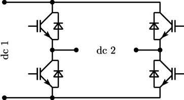
|
If the firing inputs fire_p and fire_n are inverse, the two legs are controlled symmetrically so that full positive or negative output voltage can be generated. See examples
DCDC.HBridge.
Extends from Icons.Converter (Converter icon), Modelica.Electrical.PowerConverters.Interfaces.DCDC.DCtwoPin1 (Positive and negative pins of side 1), Modelica.Electrical.PowerConverters.Interfaces.DCDC.DCtwoPin2 (Positive and negative pins of side 2), Modelica.Electrical.Analog.Interfaces.ConditionalHeatPort (Partial model to include a conditional HeatPort in order to describe the power loss via a thermal network), Interfaces.Enable.Enable2 (Partial model providing enable parameter and optional enable input for two firing signals).
| Name | Description |
|---|---|
| useHeatPort | =true, if heatPort is enabled |
| T | Fixed device temperature if useHeatPort = false [K] |
| RonTransistor | Transistor closed resistance [Ohm] |
| GoffTransistor | Transistor opened conductance [S] |
| VkneeTransistor | Transistor threshold voltage [V] |
| RonDiode | Diode closed resistance [Ohm] |
| GoffDiode | Diode opened conductance [S] |
| VkneeDiode | Diode threshold voltage [V] |
| Enable | |
| useConstantEnable | true = disabled boolean input, use constantEnable |
| constantEnable | Constant enabling of firing signals |
| Name | Description |
|---|---|
| dc_p1 | Positive DC input |
| dc_n1 | Negative DC input |
| dc_p2 | Positive DC output |
| dc_n2 | Negative DC output |
| heatPort | Conditional heat port |
| enable | Enables fire and notFire |
| fire_p | Firing signal of positive potential transistor |
| fire_n | Firing signal of negative potential transistor |