Synchronous machines
This package contains various synchronous induction machine models.
Extends from Modelica.Icons.VariantsPackage (Icon for package containing variants).
| Name | Description |
|---|---|
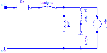
| Permanent magnet synchronous machine with optional damper cage | |
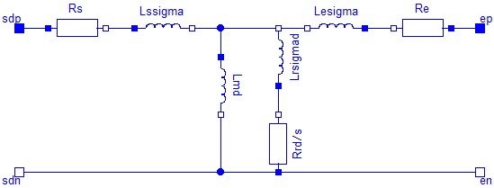
| Electrical excited synchronous machine with optional damper cage | |
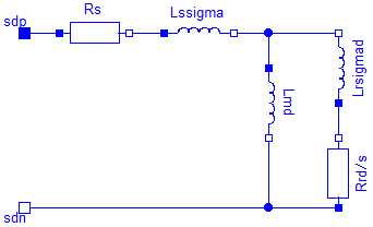
| Reluctance machine with optional damper cage |
 Modelica.Magnetic.FundamentalWave.BasicMachines.SynchronousInductionMachines.SM_PermanentMagnet
Permanent magnet synchronous machine with optional damper cage
Resistances and stray inductances of the machine refer to an m phase stator. The symmetry of the stator is assumed. For rotor asymmetries can be taken into account by different resistances and stray inductances in the d- and q-axis. The machine models take the following loss effects into account:
SM_ElectricalExcited, SM_ReluctanceRotor,
Extends from Modelica.Magnetic.FundamentalWave.Interfaces.PartialBasicInductionMachine (Partial model for induction machine).
| Name | Description |
|---|---|
| m | Number of stator phases |
| Jr | Rotor inertia [kg.m2] |
| useSupport | Enable / disable (=fixed stator) support |
| Js | Stator inertia [kg.m2] |
| useThermalPort | Enable / disable (=fixed temperatures) thermal port |
| p | Number of pole pairs (Integer) |
| fsNominal | Nominal frequency [Hz] |
| effectiveStatorTurns | Effective number of stator turns |
| VsOpenCircuit | Open circuit RMS voltage per phase @ fsNominal [V] |
| Operational temperatures | |
| TsOperational | Operational temperature of stator resistance [K] |
| TrOperational | Operational temperature of (optional) damper cage [K] |
| Initialization | |
| phiMechanical | Mechanical angle of rotor against stator [rad] |
| wMechanical | Mechanical angular velocity of rotor against stator [rad/s] |
| ir[2] | Damper cage currents [A] |
| Nominal resistances and inductances | |
| TsRef | Reference temperature of stator resistance [K] |
| alpha20s | Temperature coefficient of stator resistance at 20 degC [1/K] |
| Lszero | Stator zero inductance [H] |
| Lmd | Stator main field inductance, d-axis [H] |
 | |
| Lmq | Stator main field inductance, q-axis [H] |
| Damper cage | |
| useDamperCage | Enable/disable damper cage |
| Lrsigmad | Rotor leakage inductance, d-axis, w.r.t. stator side [H] |
| Lrsigmaq | Rotor leakage inductance, q-axis, w.r.t. stator side [H] |
| Rrd | Rotor resistance, d-axis, w.r.t. stator side [Ohm] |
| Rrq | Rotor resistance , q-axis, w.r.t. stator side [Ohm] |
| TrRef | Reference temperature of damper resistances in d- and q-axis [K] |
| alpha20r | Temperature coefficient of damper resistances in d- and q-axis [1/K] |
| Losses | |
| frictionParameters | Friction loss parameter record |
| statorCoreParameters | Stator core loss parameter record; all parameters refer to stator side |
| strayLoadParameters | Stray load loss parameter record |
| permanentMagnetLossParameters | Permanent magnet loss parameter record |
| Name | Description |
|---|---|
| flange | Shaft |
| support | Support at which the reaction torque is acting |
| plug_sp | Positive plug of stator |
| plug_sn | Negative plug of stator |
| internalSupport | |
| Initialization | |
| ir[2] | Damper cage currents [A] |
 Modelica.Magnetic.FundamentalWave.BasicMachines.SynchronousInductionMachines.SM_ElectricalExcited
Electrical excited synchronous machine with optional damper cage
The symmetry of the stator is assumed. For rotor asymmetries can be taken into account by different resistances and stray inductances in the d- and q-axis. The machine models take the following loss effects into account:
SM_PermanentMagnet, SM_ReluctanceRotor,
Extends from Modelica.Magnetic.FundamentalWave.Interfaces.PartialBasicInductionMachine (Partial model for induction machine).
| Name | Description |
|---|---|
| m | Number of stator phases |
| Jr | Rotor inertia [kg.m2] |
| useSupport | Enable / disable (=fixed stator) support |
| Js | Stator inertia [kg.m2] |
| useThermalPort | Enable / disable (=fixed temperatures) thermal port |
| p | Number of pole pairs (Integer) |
| fsNominal | Nominal frequency [Hz] |
| effectiveStatorTurns | Effective number of stator turns |
| Operational temperatures | |
| TsOperational | Operational temperature of stator resistance [K] |
| TrOperational | Operational temperature of (optional) damper cage [K] |
| TeOperational | Operational excitation temperature [K] |
| Initialization | |
| phiMechanical | Mechanical angle of rotor against stator [rad] |
| wMechanical | Mechanical angular velocity of rotor against stator [rad/s] |
| ir[2] | Damper cage currents [A] |
| Nominal resistances and inductances | |
| TsRef | Reference temperature of stator resistance [K] |
| alpha20s | Temperature coefficient of stator resistance at 20 degC [1/K] |
| Lszero | Stator zero inductance [H] |
| Lmd | Stator main field inductance, d-axis [H] |
 | |
| Lmq | Stator main field inductance, q-axis [H] |
| DamperCage | |
| useDamperCage | Enable/disable damper cage |
| Lrsigmad | Rotor leakage inductance, d-axis, w.r.t. stator side [H] |
| Lrsigmaq | Rotor leakage inductance, q-axis, w.r.t. stator side [H] |
| Rrd | Rotor resistance, d-axis, w.r.t. stator side [Ohm] |
| Rrq | Rotor resistance , q-axis, w.r.t. stator side [Ohm] |
| TrRef | Reference temperature of damper resistances in d- and q-axis [K] |
| alpha20r | Temperature coefficient of damper resistances in d- and q-axis [1/K] |
| Losses | |
| frictionParameters | Friction loss parameter record |
| statorCoreParameters | Stator core loss parameter record; all parameters refer to stator side |
| strayLoadParameters | Stray load loss parameter record |
| brushParameters | Brush loss parameter record |
| Excitation | |
| VsNominal | Nominal stator voltage [V] |
| IeOpenCircuit | Open circuit excitation current @ nominal voltage and frequency [A] |
| Re | Warm excitation resistance [Ohm] |
| TeRef | Reference temperature of excitation resistance [K] |
| alpha20e | Temperature coefficient of excitation resistance [1/K] |
| sigmae | Stray fraction of total excitation inductance |
| Name | Description |
|---|---|
| flange | Shaft |
| support | Support at which the reaction torque is acting |
| plug_sp | Positive plug of stator |
| plug_sn | Negative plug of stator |
| internalSupport | |
| irRMS | Damper cage RMS current [A] |
| pin_ep | Positive pin of excitation |
| pin_en | Negative pin of excitation |
| Initialization | |
| ir[2] | Damper cage currents [A] |
 Modelica.Magnetic.FundamentalWave.BasicMachines.SynchronousInductionMachines.SM_ReluctanceRotor
Reluctance machine with optional damper cage
The symmetry of the stator is assumed. For rotor asymmetries can be taken into account by different resistances and stray inductances in the d- and q-axis. The machine models take the following loss effects into account:
SM_ElectricalExcited, SM_PermanentMagnet,
Extends from Modelica.Magnetic.FundamentalWave.Interfaces.PartialBasicInductionMachine (Partial model for induction machine).
| Name | Description |
|---|---|
| m | Number of stator phases |
| Jr | Rotor inertia [kg.m2] |
| useSupport | Enable / disable (=fixed stator) support |
| Js | Stator inertia [kg.m2] |
| useThermalPort | Enable / disable (=fixed temperatures) thermal port |
| p | Number of pole pairs (Integer) |
| fsNominal | Nominal frequency [Hz] |
| effectiveStatorTurns | Effective number of stator turns |
| Operational temperatures | |
| TsOperational | Operational temperature of stator resistance [K] |
| TrOperational | Operational temperature of (optional) damper cage [K] |
| Initialization | |
| phiMechanical | Mechanical angle of rotor against stator [rad] |
| wMechanical | Mechanical angular velocity of rotor against stator [rad/s] |
| ir[2] | Damper cage currents [A] |
| Nominal resistances and inductances | |
| TsRef | Reference temperature of stator resistance [K] |
| alpha20s | Temperature coefficient of stator resistance at 20 degC [1/K] |
| Lszero | Stator zero inductance [H] |
| Lmd | Stator main field inductance, d-axis [H] |
 | |
| Lmq | Stator main field inductance, q-axis [H] |
| DamperCage | |
| useDamperCage | Enable/disable damper cage |
| Lrsigmad | Rotor leakage inductance, d-axis, w.r.t. stator side [H] |
| Lrsigmaq | Rotor leakage inductance, q-axis, w.r.t. stator side [H] |
| Rrd | Rotor resistance, d-axis, w.r.t. stator side [Ohm] |
| Rrq | Rotor resistance , q-axis, w.r.t. stator side [Ohm] |
| TrRef | Reference temperature of damper resistances in d- and q-axis [K] |
| alpha20r | Temperature coefficient of damper resistances in d- and q-axis [1/K] |
| Losses | |
| frictionParameters | Friction loss parameter record |
| statorCoreParameters | Stator core loss parameter record; all parameters refer to stator side |
| strayLoadParameters | Stray load loss parameter record |
| Name | Description |
|---|---|
| flange | Shaft |
| support | Support at which the reaction torque is acting |
| plug_sp | Positive plug of stator |
| plug_sn | Negative plug of stator |
| internalSupport | |
| Initialization | |
| ir[2] | Damper cage currents [A] |