Utility models for Examples.Loops
This package contains utility functions used by some of the Loops example models.
Extends from Modelica.Icons.UtilitiesPackage (Icon for utility packages).
| Name | Description |
|---|---|
| Cylinder with rod and crank of a combustion engine | |
| Simple gas force computation for combustion engine | |
| Rough approximation of gas force in a combustion engine's cylinder | |
| One cylinder with analytic handling of kinematic loop | |
| One cylinder with analytic handling of kinematic loop and CAD visualization | |
| V6 engine with analytic loop handling | |
| Model of one cylinder engine with gas force |
 Modelica.Mechanics.MultiBody.Examples.Loops.Utilities.Cylinder
Cylinder with rod and crank of a combustion engine
Cylinder with rod and crank of a combustion engine. Used as submodel in Loops.EngineV6.
| Name | Description |
|---|---|
| animation | = true, if animation shall be enabled |
| cylinderTopPosition | Length from crank shaft to end of cylinder. [m] |
| pistonLength | Length of cylinder [m] |
| rodLength | Length of rod [m] |
| crankLength | Length of crank shaft in x direction [m] |
| crankPinOffset | Offset of crank pin from center axis [m] |
| crankPinLength | Offset of crank pin from center axis [m] |
| cylinderInclination | Inclination of cylinder [rad] |
| crankAngleOffset | Offset for crank angle [rad] |
| cylinderLength | Maximum length of cylinder volume [m] |
| Name | Description |
|---|---|
| cylinder_a | |
| cylinder_b | |
| crank_a | |
| crank_b |
 Modelica.Mechanics.MultiBody.Examples.Loops.Utilities.GasForce
Simple gas force computation for combustion engine
Very simple analytic model of the force generated by the combustion in an engine cylinder.
Extends from Modelica.Icons.ObsoleteModel (Icon for classes that are obsolete and will be removed in later versions), Modelica.Mechanics.Translational.Interfaces.PartialCompliant (Compliant connection of two translational 1D flanges).
| Name | Description |
|---|---|
| L | Length of cylinder [m] |
| d | Diameter of cylinder [m] |
| k0 | Volume V = k0 + k1*(1-x), with x = 1 + s_rel/L [m3] |
| k1 | Volume V = k0 + k1*(1-x), with x = 1 + s_rel/L [m3] |
| k | Gas constant (p*V = k*T) [J/K] |
| Initialization | |
| s_rel | Relative distance (= flange_b.s - flange_a.s) [m] |
| Name | Description |
|---|---|
| flange_a | Left flange of compliant 1-dim. translational component |
| flange_b | Right flange of compliant 1-dim. translational component |
 Modelica.Mechanics.MultiBody.Examples.Loops.Utilities.GasForce2
Rough approximation of gas force in a combustion engine's cylinder
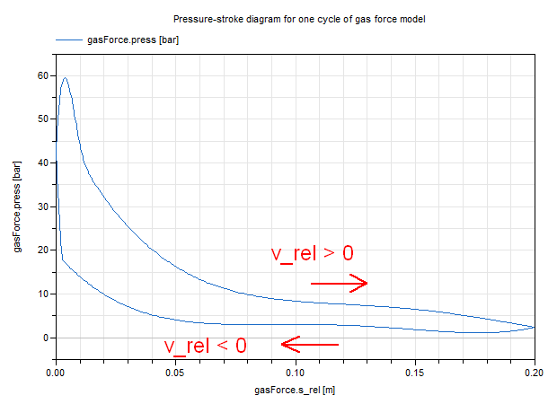
The gas force in a cylinder of a combustion engine is computed as function of the relative distance of the two flanges. It is required that s_rel = flange_b.s - flange_a.s is in the range
0 ≤ s_rel ≤ L,
where the parameter L is the length of the cylinder. If this assumption is not fulfilled, an error occurs. The resulting approximation of the gas pressure is shown in the following figure and depends on both s_rel and the relative velocity v_rel = der(s_rel).
Extends from Modelica.Mechanics.Translational.Interfaces.PartialCompliant (Compliant connection of two translational 1D flanges).
| Name | Description |
|---|---|
| L | Length of cylinder [m] |
| d | Diameter of cylinder [m] |
| k0 | Volume V = k0 + k1*(1-x), with x = 1 - s_rel/L [m3] |
| k1 | Volume V = k0 + k1*(1-x), with x = 1 - s_rel/L [m3] |
| k | Gas constant (p*V = k*T) [J/K] |
| Initialization | |
| s_rel | Relative distance (= flange_b.s - flange_a.s) [m] |
| Name | Description |
|---|---|
| flange_a | Left flange of compliant 1-dim. translational component |
| flange_b | Right flange of compliant 1-dim. translational component |
 Modelica.Mechanics.MultiBody.Examples.Loops.Utilities.CylinderBase
One cylinder with analytic handling of kinematic loop
Slider-crank mechanism with analytic handling of kinematic loop to model one cylinder in an engine.
| Name | Description |
|---|---|
| animation | = true, if animation shall be enabled |
| cylinderTopPosition | Length from crank shaft to end of cylinder. [m] |
| crankLength | Length of crank shaft in x direction [m] |
| crankPinOffset | Offset of crank pin from center axis [m] |
| crankPinLength | Offset of crank pin from center axis [m] |
| cylinderInclination | Inclination of cylinder [deg] |
| crankAngleOffset | Offset for crank angle [deg] |
| Piston | |
| pistonLength | Length of cylinder [m] |
| pistonCenterOfMass | Distance from frame_a to center of mass of piston [m] |
| pistonMass | Mass of piston [kg] |
| pistonInertia_11 | Inertia 11 of piston with respect to center of mass frame, parallel to frame_a [kg.m2] |
| pistonInertia_22 | Inertia 22 of piston with respect to center of mass frame, parallel to frame_a [kg.m2] |
| pistonInertia_33 | Inertia 33 of piston with respect to center of mass frame, parallel to frame_a [kg.m2] |
| Rod | |
| rodLength | Length of rod [m] |
| rodCenterOfMass | Distance from frame_a to center of mass of piston [m] |
| rodMass | Mass of rod [kg] |
| rodInertia_11 | Inertia 11 of rod with respect to center of mass frame, parallel to frame_a [kg.m2] |
| rodInertia_22 | Inertia 22 of rod with respect to center of mass frame, parallel to frame_a [kg.m2] |
| rodInertia_33 | Inertia 33 of rod with respect to center of mass frame, parallel to frame_a [kg.m2] |
| Name | Description |
|---|---|
| cylinder_a | |
| cylinder_b | |
| crank_a | |
| crank_b |
Modelica.Mechanics.MultiBody.Examples.Loops.Utilities.Cylinder_analytic_CADOne cylinder with analytic handling of kinematic loop and CAD visualization
Slider-crank mechanism with analytic handling of kinematic loop to model one cylinder in an engine.
Extends from CylinderBase (One cylinder with analytic handling of kinematic loop).
| Name | Description |
|---|---|
| animation | = true, if animation shall be enabled |
| cylinderTopPosition | Length from crank shaft to end of cylinder. [m] |
| crankLength | Length of crank shaft in x direction [m] |
| crankPinOffset | Offset of crank pin from center axis [m] |
| crankPinLength | Offset of crank pin from center axis [m] |
| cylinderInclination | Inclination of cylinder [deg] |
| crankAngleOffset | Offset for crank angle [deg] |
| Piston | |
| pistonLength | Length of cylinder [m] |
| pistonCenterOfMass | Distance from frame_a to center of mass of piston [m] |
| pistonMass | Mass of piston [kg] |
| pistonInertia_11 | Inertia 11 of piston with respect to center of mass frame, parallel to frame_a [kg.m2] |
| pistonInertia_22 | Inertia 22 of piston with respect to center of mass frame, parallel to frame_a [kg.m2] |
| pistonInertia_33 | Inertia 33 of piston with respect to center of mass frame, parallel to frame_a [kg.m2] |
| Rod | |
| rodLength | Length of rod [m] |
| rodCenterOfMass | Distance from frame_a to center of mass of piston [m] |
| rodMass | Mass of rod [kg] |
| rodInertia_11 | Inertia 11 of rod with respect to center of mass frame, parallel to frame_a [kg.m2] |
| rodInertia_22 | Inertia 22 of rod with respect to center of mass frame, parallel to frame_a [kg.m2] |
| rodInertia_33 | Inertia 33 of rod with respect to center of mass frame, parallel to frame_a [kg.m2] |
| Name | Description |
|---|---|
| cylinder_a | |
| cylinder_b | |
| crank_a | |
| crank_b |
 Modelica.Mechanics.MultiBody.Examples.Loops.Utilities.EngineV6_analytic
V6 engine with analytic loop handling
Model of an engine with 6 cylinders where the algebraic loops of the slider crank mechanisms are solved analytically.
| Name | Description |
|---|---|
| animation | = true, if animation shall be enabled |
| replaceable model Cylinder | Cylinder type |
| Name | Description |
|---|---|
| replaceable model Cylinder | Cylinder type |
| flange_b | |
| frame_a |
Model of one cylinder engine with gas force
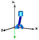
This is a model of the mechanical part of one cylinder of an engine. The combustion is not modelled. The "inertia" component at the lower left part is the output inertia of the engine driving the gearbox. The angular velocity of the output inertia has a start value of 10 rad/s in order to demonstrate the movement of the engine.
The engine is modeled solely by revolute and prismatic joints. Since this results in a planar loop there is the well known difficulty that the cut-forces perpendicular to the loop cannot be uniquely computed, as well as the cut-torques within the plane. This ambiguity is resolved by using the option planarCutJoint in the Advanced menu of one revolute joint in every planar loop (here: joint B1). This option sets the cut-force in direction of the axis of rotation, as well as the cut-torques perpendicular to the axis of rotation at this joint to zero and makes the problem mathematically well-formed.
An animation of this example is shown in the figure below.
 Automatically generated Thu Dec 19 17:20:06 2019.