Library to demonstrate robot system models based on the Manutec r3 robot
This package contains models of the robot r3 of the company Manutec. These models are used to demonstrate in which way complex robot models might be built up by testing first the component models individually before composing them together. Furthermore, it is shown how CAD data can be used for animation.
The following models are available:
   oneAxis   Test one axis (controller, motor, gearbox).
   fullRobot Test complete robot model.
The r3 robot is no longer manufactured. In fact the company Manutec does no longer exist. The parameters of this robot have been determined by measurements in the laboratory of DLR. The measurement procedure is described in:
   Tuerk S. (1990): Zur Modellierung der Dynamik von Robotern mit
       rotatorischen Gelenken. Fortschrittberichte VDI, Reihe 8, Nr. 211,
       VDI-Verlag 1990.
The robot model is described in detail in
   Otter M. (1995): Objektorientierte Modellierung mechatronischer
       Systeme am Beispiel geregelter Roboter. Dissertation,
       Fortschrittberichte VDI, Reihe 20, Nr. 147, VDI-Verlag 1995.
       This report can be downloaded as compressed postscript file
       from: http://www.robotic.dlr.de/Martin.Otter.
The path planning is performed in a simple way by using essentially the Modelica.Mechanics.Rotational.KinematicPTP block. A user defines a path by start and end angle of every axis. A path is planned such that all axes are moving as fast as possible under the given restrictions of maximum joint speeds and maximum joint accelerations. The actual r3 robot from Manutec had a different path planning strategy. Today's path planning algorithms from robot companies are much more involved.
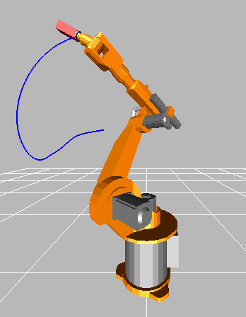
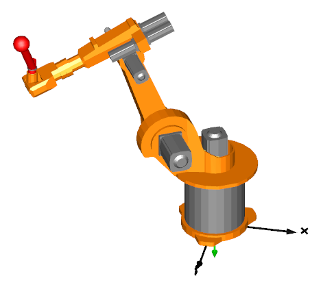
In order to get a nice animation, CAD data from a KUKA robot is used, since CAD data of the original r3 robot was not available. The KUKA CAD data was derived from public data of KUKA. Since dimensions of the corresponding KUKA robot are similar but not identical to the r3 robot, the data of the r3 robot (such as arm lengths) have been modified, such that it matches the CAD data.
In this model, a simplified P-PI cascade controller for every axes is used. The parameters have been manually adjusted by simulations. The original r3 controllers are more complicated. The reason to use simplified controllers is to have a simpler demo.
Extends from Modelica.Icons.ExamplesPackage (Icon for packages containing runnable examples).
| Name | Description |
|---|---|
| Model of one axis of robot (controller, motor, gearbox) with simple load | |
| Six degree of freedom robot with path planning, controllers, motors, brakes, gears and mechanics | |
| Library of components of the robot |
 Modelica.Mechanics.MultiBody.Examples.Systems.RobotR3.oneAxis
Model of one axis of robot (controller, motor, gearbox) with simple load
With this model one axis of the r3 robot is checked. The mechanical structure is replaced by a simple load inertia.
Extends from Modelica.Icons.Example (Icon for runnable examples).
| Name | Description |
|---|---|
| mLoad | Mass of load [kg] |
| kp | Gain of position controller of axis 2 |
| ks | Gain of speed controller of axis 2 |
| Ts | Time constant of integrator of speed controller of axis 2 [s] |
| startAngle | Start angle of axis 2 [deg] |
| endAngle | End angle of axis 2 [deg] |
| swingTime | Additional time after reference motion is in rest before simulation is stopped [s] |
| refSpeedMax | Maximum reference speed [rad/s] |
| refAccMax | Maximum reference acceleration [rad/s2] |
Modelica.Mechanics.MultiBody.Examples.Systems.RobotR3.fullRobotSix degree of freedom robot with path planning, controllers, motors, brakes, gears and mechanics
This example animates a motion of a detailed model of the robot with predefined axes' angles over time. For animation, CAD data is used. Translate and simulate with the default settings (default simulation stop time = 2 s).
The path planning block incorporates a simulation termination condition. Thus, the simulation can be terminated before reaching the stop time. The condition depends on the start and end positions of the joints, and on their reference speeds and reference accelerations. For current settings, the termination condition should indeed be fulfilled right before the simulation stops.
Extends from Modelica.Icons.Example (Icon for runnable examples).
| Name | Description |
|---|---|
| mLoad | Mass of load [kg] |
| rLoad[3] | Distance from last flange to load mass [m] |
| g | Gravity acceleration [m/s2] |
| refStartTime | Start time of reference motion [s] |
| refSwingTime | Additional time after reference motion is in rest before simulation is stopped [s] |
| Reference | |
| startAngles | |
| startAngle1 | Start angle of axis 1 [deg] |
| startAngle2 | Start angle of axis 2 [deg] |
| startAngle3 | Start angle of axis 3 [deg] |
| startAngle4 | Start angle of axis 4 [deg] |
| startAngle5 | Start angle of axis 5 [deg] |
| startAngle6 | Start angle of axis 6 [deg] |
| endAngles | |
| endAngle1 | End angle of axis 1 [deg] |
| endAngle2 | End angle of axis 2 [deg] |
| endAngle3 | End angle of axis 3 [deg] |
| endAngle4 | End angle of axis 4 [deg] |
| endAngle5 | End angle of axis 5 [deg] |
| endAngle6 | End angle of axis 6 [deg] |
| Limits | |
| refSpeedMax[6] | Maximum reference speeds of all joints [rad/s] |
| refAccMax[6] | Maximum reference accelerations of all joints [rad/s2] |
| Controller | |
| Axis 1 | |
| kp1 | Gain of position controller |
| ks1 | Gain of speed controller |
| Ts1 | Time constant of integrator of speed controller [s] |
| Axis 2 | |
| kp2 | Gain of position controller |
| ks2 | Gain of speed controller |
| Ts2 | Time constant of integrator of speed controller [s] |
| Axis 3 | |
| kp3 | Gain of position controller |
| ks3 | Gain of speed controller |
| Ts3 | Time constant of integrator of speed controller [s] |
| Axis 4 | |
| kp4 | Gain of position controller |
| ks4 | Gain of speed controller |
| Ts4 | Time constant of integrator of speed controller [s] |
| Axis 5 | |
| kp5 | Gain of position controller |
| ks5 | Gain of speed controller |
| Ts5 | Time constant of integrator of speed controller [s] |
| Axis 6 | |
| kp6 | Gain of position controller |
| ks6 | Gain of speed controller |
| Ts6 | Time constant of integrator of speed controller [s] |