Adder44 Bit Adder Example |
|
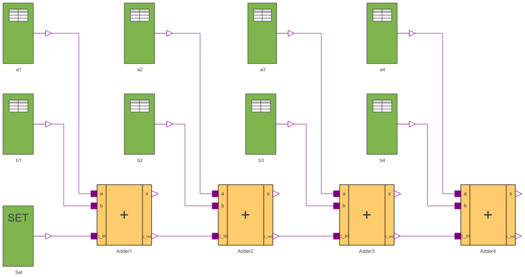
Diagram
Information
This information is part of the Modelica Standard Library maintained by the Modelica Association.
Four FullAdders are combined to built a four bit adder unit.
In dependence on time five additions are carried out:
at t = 0                            at t = 1
 a       0 0 0 0                       a      1 1 1 0
 b    +  0 0 0 0                       b   +  1 0 1 1
 s     0 0 0 0 0                      s     1 0 0 1 0
at t = 2                             at t = 3
 a       0 1 1 0                       a      1 1 1 0
 b    +  0 0 1 1                       b   +  1 0 1 0
 s     1 0 1 0 0                      s     0 0 0 1 1

at t = 4
 a      1 1 0 0
 b   +  1 1 1 0
 s    0 0 1 0 1
To show the influence of delay a large delay time of 0.1s is chosen. Furthermore, all signals are initialized with U, the uninitialized value. Please remember, that the nine logic values are coded by the numbers 1,...,9. The summands a and b can be found at the output signals of the taba and tabb sources. The result can be seen in the output signals of the FullAdders according to:
      a                       a4.y      a3.y      a2.y      a1.y
      b                       b4.y      b3.y      b2.y      b1.y
      sum   Adder4.c_out  Adder4.s  Adder3.s  Adder2.s  Adder1.s
The simulation stop time has to be 5s.