Flow models for pipes, including wall friction, static head and momentum flow
Extends from Modelica.Icons.Package (Icon for standard packages).
| Name | Description |
|---|---|
| Base class for momentum balances in flow models | |
| NominalLaminarFlow: Linear laminar flow for given nominal values | |
| GenericPipeFlow: Pipe flow pressure loss and gravity with replaceable WallFriction package | |
| NominalTurbulentPipeFlow: Quadratic turbulent flow in circular tubes for given nominal values | |
| TurbulentPipeFlow: Quadratic turbulent flow in circular tubes (using mu to regularize laminar region) | |
| DetailedPipeFlow: Detailed characteristic for laminar and turbulent flow |
 Modelica.Fluid.Pipes.BaseClasses.FlowModels.PartialStaggeredFlowModel
Base class for momentum balances in flow models
This partial model defines a common interface for m=n-1 flow models between n device segments.
The flow models provide a steady-state or dynamic momentum balance using an upwind discretization scheme per default.
Extending models must add pressure loss terms for friction and gravity.
The fluid is specified in the interface with the thermodynamic states[n] for a given Medium model.
The geometry is specified with the pathLengths[n-1] between the device segments as well as
with the crossAreas[n] and the roughnesses[n] of the device segments.
Moreover the fluid flow is characterized for different types of devices by the characteristic dimensions[n]
and the average velocities vs[n] of fluid flow in the device segments.
See Pipes.BaseClasses.CharacteristicNumbers.ReynoldsNumber
for example definitions.
The parameter Re_turbulent can be specified for the least mass flow rate of the turbulent regime.
It defaults to 4000, which is appropriate for pipe flow.
The m_flows_turbulent[n-1] resulting from Re_turbulent can optionally be calculated together with the Reynolds numbers
Res[n] of the device segments (show_Res=true).
Using the thermodynamic states[n] of the device segments, the densities rhos[n] and the dynamic viscosities mus[n] of the segments as well as the actual densities rhos_act[n-1] and the actual viscosities mus_act[n-1] of the flows are predefined in this base model. Note that no events are raised on flow reversal. This needs to be treated by an extending model, e.g., with numerical smoothing or by raising events as appropriate.
Extends from Modelica.Fluid.Interfaces.PartialDistributedFlow (Base class for a distributed momentum balance).
| Name | Description |
|---|---|
| m | Number of flow segments |
| Re_turbulent | Start of turbulent regime, depending on type of flow device [1] |
| Advanced | |
| useUpstreamScheme | = false to average upstream and downstream properties across flow segments |
| use_Ib_flows | = true to consider differences in flow of momentum through boundaries |
| Diagnostics | |
| show_Res | = true, if Reynolds numbers are included for plotting |
| Internal interface | |
| replaceable package Medium | Medium in the component |
| n | Number of discrete flow volumes |
| Geometry | |
| nParallel | Number of identical parallel flow devices |
| Static head | |
| g | Constant gravity acceleration [m/s2] |
| Assumptions | |
| allowFlowReversal | = true, if flow reversal is enabled, otherwise restrict flow to design direction (states[1] -> states[n+1]) |
| momentumDynamics | Formulation of momentum balance |
| Initialization | |
| m_flow_start | Start value of mass flow rates [kg/s] |
| p_a_start | Start value for p[1] at design inflow [Pa] |
| p_b_start | Start value for p[n+1] at design outflow [Pa] |
| Name | Description |
|---|---|
| Internal interface | |
| replaceable package Medium | Medium in the component |
 Modelica.Fluid.Pipes.BaseClasses.FlowModels.NominalLaminarFlow
NominalLaminarFlow: Linear laminar flow for given nominal values
This model defines a simple linear pressure loss assuming laminar flow for
specified dp_nominal and m_flow_nominal.
Select show_Res = true to analyze the actual flow and the lengths of a pipe that would fulfill the
specified nominal values for given geometry parameters crossAreas, dimensions and roughnesses.
Extends from Modelica.Fluid.Pipes.BaseClasses.FlowModels.PartialStaggeredFlowModel (Base class for momentum balances in flow models).
| Name | Description |
|---|---|
| Re_turbulent | Start of turbulent regime, depending on type of flow device [1] |
| dp_nominal | Nominal pressure loss [Pa] |
| m_flow_nominal | Mass flow rate for dp_nominal [kg/s] |
| Advanced | |
| useUpstreamScheme | = false to average upstream and downstream properties across flow segments |
| use_Ib_flows | = true to consider differences in flow of momentum through boundaries |
| Diagnostics | |
| show_Res | = true, if Reynolds numbers are included for plotting |
| Internal interface | |
| replaceable package Medium | Medium in the component |
| n | Number of discrete flow volumes |
| Geometry | |
| nParallel | Number of identical parallel flow devices |
| Static head | |
| g | Constant gravity acceleration [m/s2] |
| Assumptions | |
| allowFlowReversal | = true, if flow reversal is enabled, otherwise restrict flow to design direction (states[1] -> states[n+1]) |
| momentumDynamics | Formulation of momentum balance |
| Initialization | |
| m_flow_start | Start value of mass flow rates [kg/s] |
| p_a_start | Start value for p[1] at design inflow [Pa] |
| p_b_start | Start value for p[n+1] at design outflow [Pa] |
 Modelica.Fluid.Pipes.BaseClasses.FlowModels.PartialGenericPipeFlow
GenericPipeFlow: Pipe flow pressure loss and gravity with replaceable WallFriction package
This model describes pressure losses due to wall friction in a pipe and due to gravity. Correlations of different complexity and validity can be selected via the replaceable package WallFriction (see parameter menu below). The details of the pipe wall friction model are described in the UsersGuide. Basically, different variants of the equation
dp = λ(Re,Δ)*(L/D)*ρ*v*|v|/2.
By default, the correlations are computed with media data at the actual time instant. In order to reduce non-linear equation systems, the parameters use_mu_nominal and use_rho_nominal provide the option to compute the correlations with constant media values at the desired operating point. This might speed-up the simulation and/or might give a more robust simulation.
Extends from Modelica.Fluid.Pipes.BaseClasses.FlowModels.PartialStaggeredFlowModel (Base class for momentum balances in flow models).
| Name | Description |
|---|---|
| Re_turbulent | Start of turbulent regime, depending on type of flow device [1] |
| dp_nominal | Nominal pressure loss (only for nominal models) [Pa] |
| m_flow_nominal | Nominal mass flow rate [kg/s] |
| m_flow_small | Within regularization if |m_flows| < m_flow_small (may be wider for large discontinuities in static head) [kg/s] |
| Advanced | |
| from_dp | = true, use m_flow = f(dp), otherwise dp = f(m_flow) |
| useUpstreamScheme | = false to average upstream and downstream properties across flow segments |
| use_Ib_flows | = true to consider differences in flow of momentum through boundaries |
| Diagnostics | |
| show_Res | = true, if Reynolds numbers are included for plotting |
| Wall friction | |
| replaceable package WallFriction | Wall friction model |
| Internal interface | |
| replaceable package Medium | Medium in the component |
| n | Number of discrete flow volumes |
| Geometry | |
| nParallel | Number of identical parallel flow devices |
| Static head | |
| g | Constant gravity acceleration [m/s2] |
| Assumptions | |
| allowFlowReversal | = true, if flow reversal is enabled, otherwise restrict flow to design direction (states[1] -> states[n+1]) |
| momentumDynamics | Formulation of momentum balance |
| Initialization | |
| m_flow_start | Start value of mass flow rates [kg/s] |
| p_a_start | Start value for p[1] at design inflow [Pa] |
| p_b_start | Start value for p[n+1] at design outflow [Pa] |
| Name | Description |
|---|---|
| Wall friction | |
| replaceable package WallFriction | Wall friction model |
 Modelica.Fluid.Pipes.BaseClasses.FlowModels.NominalTurbulentPipeFlow
NominalTurbulentPipeFlow: Quadratic turbulent flow in circular tubes for given nominal values
This model defines the pressure loss assuming turbulent flow for
specified dp_nominal and m_flow_nominal.
It takes into account the fluid density of each flow segment and
obtains appropriate pathLengths_nominal values
for an inverse parameterization of the
TurbulentPipeFlow
model. Per default the upstream and downstream densities are averaged with the setting useUpstreamScheme = false,
in order to avoid discontinuous pathLengths_nominal values in the case of flow reversal.
The geometry parameters crossAreas, diameters and roughnesses do
not effect simulation results of this nominal pressure loss model.
As the geometry is specified however, the optionally calculated Reynolds number as well as
m_flows_turbulent and dps_fg_turbulent become meaningful
and can be related to m_flow_small and dp_small.
Optional Variables if show_Res
| Type | Name | Description |
|---|---|---|
| ReynoldsNumber | Res[n] | Reynolds numbers of pipe flow per flow segment |
| MassFlowRate | m_flows_turbulent[n-1] | mass flow rates at start of turbulent region for Re_turbulent=4000 |
| AbsolutePressure | dps_fg_turbulent[n-1] | pressure losses due to friction and gravity corresponding to m_flows_turbulent |
Extends from Modelica.Fluid.Pipes.BaseClasses.FlowModels.PartialGenericPipeFlow (GenericPipeFlow: Pipe flow pressure loss and gravity with replaceable WallFriction package).
| Name | Description |
|---|---|
| dp_nominal | Nominal pressure loss (only for nominal models) [Pa] |
| m_flow_nominal | Nominal mass flow rate [kg/s] |
| m_flow_small | Within regularization if |m_flows| < m_flow_small (may be wider for large discontinuities in static head) [kg/s] |
| m_flow_turbulent | Turbulent flow starting from |m_flows| > m_flow_turbulent (may be wider for large discontinuities in static head) [kg/s] |
| Advanced | |
| from_dp | = true, use m_flow = f(dp), otherwise dp = f(m_flow) |
| useUpstreamScheme | = false to average upstream and downstream properties across flow segments |
| use_Ib_flows | = true to consider differences in flow of momentum through boundaries |
| Diagnostics | |
| show_Res | = true, if Reynolds numbers are included for plotting |
| Wall friction | |
| replaceable package WallFriction | Wall friction model |
| Custom Parameters | |
| pathLengths_internal[n - 1] | pathLengths used internally; to be defined by extending class [m] |
| Res_turbulent_internal[n - 1] | Re_turbulent used internally; to be defined by extending class [1] |
| Internal interface | |
| replaceable package Medium | Medium in the component |
| n | Number of discrete flow volumes |
| Geometry | |
| nParallel | Number of identical parallel flow devices |
| Static head | |
| g | Constant gravity acceleration [m/s2] |
| Assumptions | |
| allowFlowReversal | = true, if flow reversal is enabled, otherwise restrict flow to design direction (states[1] -> states[n+1]) |
| momentumDynamics | Formulation of momentum balance |
| Initialization | |
| m_flow_start | Start value of mass flow rates [kg/s] |
| p_a_start | Start value for p[1] at design inflow [Pa] |
| p_b_start | Start value for p[n+1] at design outflow [Pa] |
| Name | Description |
|---|---|
| Wall friction | |
| replaceable package WallFriction | Wall friction model |
 Modelica.Fluid.Pipes.BaseClasses.FlowModels.TurbulentPipeFlow
TurbulentPipeFlow: Quadratic turbulent flow in circular tubes (using mu to regularize laminar region)
This model defines only the quadratic turbulent regime of wall friction: dp = k*m_flow*|m_flow|, where "k" depends on density and the roughness of the pipe and is not a function of the Reynolds number. This relationship is only valid for large Reynolds numbers. The turbulent pressure loss correlation might be useful to optimize models that are only facing turbulent flow.
Extends from Modelica.Fluid.Pipes.BaseClasses.FlowModels.PartialGenericPipeFlow (GenericPipeFlow: Pipe flow pressure loss and gravity with replaceable WallFriction package).
| Name | Description |
|---|---|
| m_flow_nominal | Nominal mass flow rate [kg/s] |
| m_flow_small | Within regularization if |m_flows| < m_flow_small (may be wider for large discontinuities in static head) [kg/s] |
| use_Re | = true, if turbulent region is defined by Re, otherwise by m_flow_small |
| Advanced | |
| from_dp | = true, use m_flow = f(dp), otherwise dp = f(m_flow) |
| useUpstreamScheme | = false to average upstream and downstream properties across flow segments |
| use_Ib_flows | = true to consider differences in flow of momentum through boundaries |
| Diagnostics | |
| show_Res | = true, if Reynolds numbers are included for plotting |
| Wall friction | |
| replaceable package WallFriction | Wall friction model |
| Custom Parameters | |
| pathLengths_internal[n - 1] | pathLengths used internally; to be defined by extending class [m] |
| Res_turbulent_internal[n - 1] | Re_turbulent used internally; to be defined by extending class [1] |
| Internal interface | |
| replaceable package Medium | Medium in the component |
| n | Number of discrete flow volumes |
| Geometry | |
| nParallel | Number of identical parallel flow devices |
| Static head | |
| g | Constant gravity acceleration [m/s2] |
| Assumptions | |
| allowFlowReversal | = true, if flow reversal is enabled, otherwise restrict flow to design direction (states[1] -> states[n+1]) |
| momentumDynamics | Formulation of momentum balance |
| Initialization | |
| m_flow_start | Start value of mass flow rates [kg/s] |
| p_a_start | Start value for p[1] at design inflow [Pa] |
| p_b_start | Start value for p[n+1] at design outflow [Pa] |
| Name | Description |
|---|---|
| Wall friction | |
| replaceable package WallFriction | Wall friction model |
 Modelica.Fluid.Pipes.BaseClasses.FlowModels.DetailedPipeFlow
DetailedPipeFlow: Detailed characteristic for laminar and turbulent flow
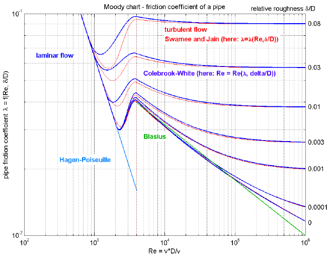
This component defines the complete regime of wall friction. The details are described in the UsersGuide. The functional relationship of the friction loss factor λ is displayed in the next figure. Function massFlowRate_dp() defines the "red curve" ("Swamee and Jain"), where as function pressureLoss_m_flow() defines the "blue curve" ("Colebrook-White"). The two functions are inverses from each other and give slightly different results in the transition region between Re = 1500 .. 4000, in order to get explicit equations without solving a non-linear equation.

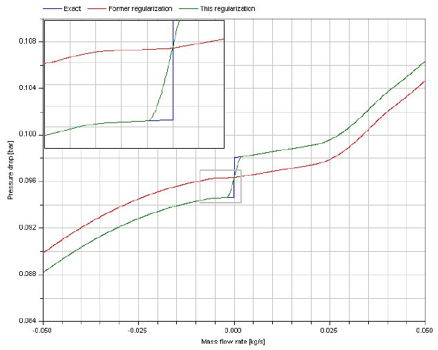
Additionally to wall friction, this component properly implements static head. With respect to the latter, two cases can be distinguished. In the case shown next, the change of elevation with the path from a to b has the opposite sign of the change of density.

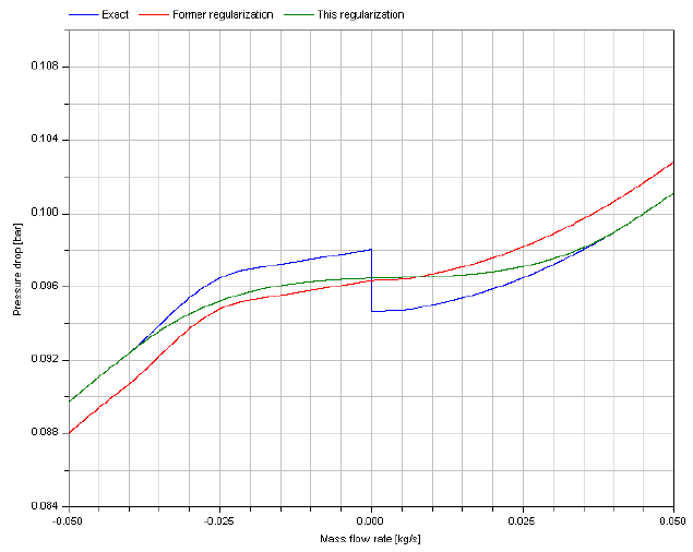
In the case illustrated second, the change of elevation with the path from a to b has the same sign of the change of density.

Extends from Modelica.Fluid.Pipes.BaseClasses.FlowModels.PartialGenericPipeFlow (GenericPipeFlow: Pipe flow pressure loss and gravity with replaceable WallFriction package).
| Name | Description |
|---|---|
| m_flow_nominal | Nominal mass flow rate [kg/s] |
| m_flow_small | Within regularization if |m_flows| < m_flow_small (may be wider for large discontinuities in static head) [kg/s] |
| Advanced | |
| from_dp | = true, use m_flow = f(dp), otherwise dp = f(m_flow) |
| useUpstreamScheme | = false to average upstream and downstream properties across flow segments |
| use_Ib_flows | = true to consider differences in flow of momentum through boundaries |
| Diagnostics | |
| show_Res | = true, if Reynolds numbers are included for plotting |
| Wall friction | |
| replaceable package WallFriction | Wall friction model |
| Custom Parameters | |
| pathLengths_internal[n - 1] | pathLengths used internally; to be defined by extending class [m] |
| Res_turbulent_internal[n - 1] | Re_turbulent used internally; to be defined by extending class [1] |
| Internal interface | |
| replaceable package Medium | Medium in the component |
| n | Number of discrete flow volumes |
| Geometry | |
| nParallel | Number of identical parallel flow devices |
| Static head | |
| g | Constant gravity acceleration [m/s2] |
| Assumptions | |
| allowFlowReversal | = true, if flow reversal is enabled, otherwise restrict flow to design direction (states[1] -> states[n+1]) |
| momentumDynamics | Formulation of momentum balance |
| Initialization | |
| m_flow_start | Start value of mass flow rates [kg/s] |
| p_a_start | Start value for p[1] at design inflow [Pa] |
| p_b_start | Start value for p[n+1] at design outflow [Pa] |
| Name | Description |
|---|---|
| Wall friction | |
| replaceable package WallFriction | Wall friction model |