TotalHarmonicDistortionCalculation of total harmonic distortion of voltage |
|
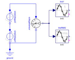
Diagram
Information
This information is part of the Modelica Standard Library maintained by the Modelica Association.
This example compares the result of the total harmonic distortion (THD) with respect to the fundamental wave and with respect to the total root mean square (RMS). In this simulation model a non-sinusoidal voltage wave form is created by the superposition two voltage waves:
- Fundamental wave with RMS voltage
V1and frequencyf1 - Third harmonic wave with RMS voltage
V3and frequency3*f1
This simulation model compares numerically determined THD values with results, obtained by theoretical calculations:
- Compare the numerically determined THD value
thd1.yand the theoretical valueTHD1, both with respect to the fundamental wave; also plotthd1.valid - Compare the numerically determined THD value
thdRMS.yand the theoretical valueTHDrms, both with respect to the RMS value; also plotthdRMS.valid
Parameters (5)
| f1 |
Value: 50 Type: Frequency (Hz) Description: Fundamental wave frequency |
|---|---|
| V1 |
Value: 100 Type: Voltage (V) Description: Fundamental wave RMS voltage |
| V3 |
Value: 20 Type: Voltage (V) Description: Third harmonic wave RMS voltage |
| THD1 |
Value: V3 / V1 Type: Real Description: Theoretically obtained THD with respect to fundamental wave |
| THDrms |
Value: V3 / sqrt(V1 ^ 2 + V3 ^ 2) Type: Real Description: Theoretically obtained THD with respect to RMS |
Components (6)
| ground |
Type: Ground |
|
|---|---|---|
| sineVoltage3 |
Type: SineVoltage |
|
| sineVoltage1 |
Type: SineVoltage |
|
| voltageSensor |
Type: VoltageSensor |
|
| thd1 |
Type: TotalHarmonicDistortion |
|
| thdRMS |
Type: TotalHarmonicDistortion |
