HighPassHigh-pass filter |
|
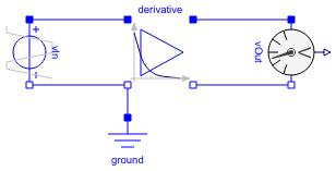
Diagram
Information
This information is part of the Modelica Standard Library maintained by the Modelica Association.
This is a (inverting) high pass filter. Resistance R1 can be chosen, resistance R2 is defined by the desired amplification k, capacitance C is defined by the desired cut-off frequency.
The example is taken from: U. Tietze and C. Schenk, Halbleiter-Schaltungstechnik (German), 11th edition, Springer 1999, Chapter 13.3
Note: vOut measure the negative output voltage.
Parameters (3)
Components (4)
| ground |
Type: Ground |
|
|---|---|---|
| vOut |
Type: VoltageSensor |
|
| derivative |
Type: Derivative |
|
| vIn |
Type: TrapezoidVoltage |