Dimmer_RLDimmer with resistive-inductive load |
|
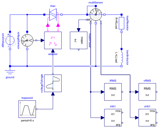
Diagram
Information
This information is part of the Modelica Standard Library maintained by the Modelica Association.
This model demonstrates the behaviour of a dimmer with phase-angle control with resistive-inductive load. Note that due to the inductance the current is not zero at the points in time wehre zero-crossing of the voltage occurs, and the triac stays conducting until the current becomes zero.
The reference voltage is prescribed by a trapezoid between zero and full voltage. The voltageToAngle block calculates the necessary phase angle, which is processed by the Signal2mPulse adaptor, applying the firing signals to the triac.
Parameters (7)
| f |
Value: 50 Type: Frequency (Hz) Description: Source frequency |
|---|---|
| Vrms |
Value: 110 Type: Voltage (V) Description: RMS source voltage |
| S |
Value: 1000 Type: ApparentPower (V·A) Description: Load apparent power |
| powerFactor |
Value: 0.87 Type: Real Description: Load power factor |
| ZLoad |
Value: Vrms ^ 2 / S Type: Impedance (Ω) Description: Load impedance |
| RLoad |
Value: ZLoad * powerFactor Type: Resistance (Ω) Description: Load resistance |
| LLoad |
Value: ZLoad * sqrt(1 - powerFactor ^ 2) / (2 * pi * f) Type: Inductance (H) Description: Load inductance |
Components (15)
| sineVoltage |
Type: SineVoltage |
|
|---|---|---|
| ground |
Type: Ground |
|
| triac |
Type: SinglePhaseTriac |
|
| voltageSensor |
Type: VoltageSensor |
|
| adaptor |
Type: Signal2mPulse |
|
| multiSensor |
Type: MultiSensor |
|
| voltageToAngle |
Type: VoltageToAngle |
|
| trapezoid |
Type: Trapezoid |
|
| meanPower |
Type: Mean |
|
| vRMS |
Type: RootMeanSquare |
|
| vH01 |
Type: Harmonic |
|
| iRMS |
Type: RootMeanSquare |
|
| iH01 |
Type: Harmonic |
|
| loadResistor |
Type: Resistor |
|
| loadInductor |
Type: Inductor |