ThyristorCenterTapmPulse_RLV2*m pulse thyristor rectifier with center tap and R-L load and voltage |
|
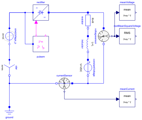
Diagram
Information
This information is part of the Modelica Standard Library maintained by the Modelica Association.
This example shows a controlled m pulse center tap rectifier with R-L load including DC voltage source, where m is the number of phases. The additional DC voltage source in this example enables negative average load voltages.
Plot current currentSensor.i, average current meanCurrent.y, voltage voltageSensor.v and average voltage meanVoltage.v.
Parameters (7)
| m |
Value: 3 Type: Integer Description: Number of phases |
|---|---|
| Vrms |
Value: 110 Type: Voltage (V) Description: RMS supply voltage |
| f |
Value: 50 Type: Frequency (Hz) Description: Frequency |
| constantFiringAngle |
Value: 30 * pi / 180 Type: Angle (rad) Description: Firing angle |
| R |
Value: 20 Type: Resistance (Ω) Description: Load resistance |
| L |
Value: 1 Type: Inductance (H) Description: Load resistance |
| VDC |
Value: -50 Type: Voltage (V) Description: DC load offset voltage |
Components (13)
| ground |
Type: Ground |
|
|---|---|---|
| star |
Type: Star |
|
| sineVoltage_p |
Type: SineVoltage |
|
| rectifier |
Type: ThyristorCenterTapmPulse |
|
| voltagesensor |
Type: VoltageSensor |
|
| meanVoltage |
Type: Mean |
|
| rootMeanSquareVoltage |
Type: RootMeanSquare |
|
| currentSensor |
Type: CurrentSensor |
|
| meanCurrent |
Type: Mean |
|
| pulsem |
Type: VoltageBridge2mPulse |
|
| resistor |
Type: Resistor |
|
| inductor |
Type: Inductor |
|
| constantVoltage |
Type: ConstantVoltage |