ChopperStepDown_RLStep down chopper with R-L load |
|
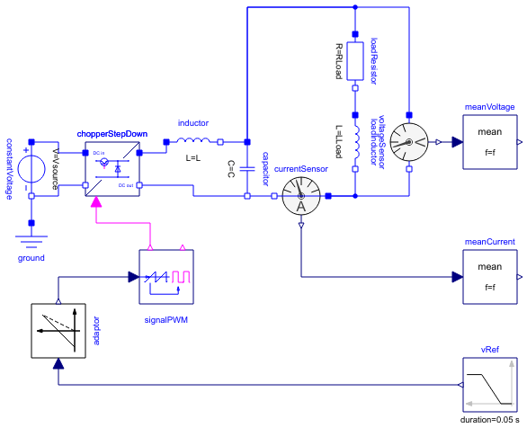
Diagram
Information
This information is part of the Modelica Standard Library maintained by the Modelica Association.
This example demonstrates the switching on of an R-L load operated by a step down chopper.
DC output voltage is equal to dutyCycle times the input voltage.
Plot current currentSensor.i, averaged current meanCurrent.y, total voltage voltageSensor.v and voltage meanVoltage.v. The waveform the average current is determined by the time constant L/R of the load.
Parameters (9)
| f |
Value: 1000 Type: Frequency (Hz) Description: Switching frequency |
|---|---|
| Vsource |
Value: 60 Type: Voltage (V) Description: Source voltage |
| L |
Value: 25e-3 Type: Inductance (H) Description: Source inductance |
| C |
Value: 20e-6 Type: Capacitance (F) Description: Smoothing capacitance |
| dutyCycle |
Value: 0.20 Type: Real Description: Duty cycle |
| ILoad |
Value: 1.2 Type: Current (A) Description: Load current |
| RLoad |
Value: V0 / ILoad Type: Resistance (Ω) Description: Load resistance |
| V0 |
Value: Vsource * dutyCycle Type: Voltage (V) Description: No-load output voltage |
| LLoad |
Value: 0.025 Type: Inductance (H) Description: Load inductance |
Components (14)
| constantVoltage |
Type: ConstantVoltage |
|
|---|---|---|
| chopperStepDown |
Type: ChopperStepDown |
|
| currentSensor |
Type: CurrentSensor |
|
| voltageSensor |
Type: VoltageSensor |
|
| ground |
Type: Ground |
|
| signalPWM |
Type: SignalPWM |
|
| meanCurrent |
Type: Mean |
|
| meanVoltage |
Type: Mean |
|
| inductor |
Type: Inductor |
|
| capacitor |
Type: Capacitor |
|
| loadResistor |
Type: Resistor |
|
| loadInductor |
Type: Inductor |
|
| adaptor |
Type: Voltage2DutyCycle |
|
| vRef |
Type: Ramp |