ChopperStepUp_RStep up chopper with resistive load |
|
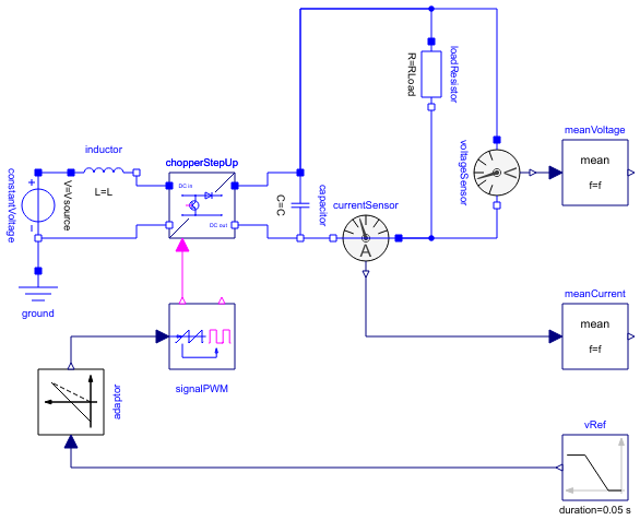
Diagram
Information
This information is part of the Modelica Standard Library maintained by the Modelica Association.
This example demonstrates the switching on of a resistive load operated by a step up chopper.
DC output voltage is equal to 1/(1 - dutyCycle) times the input voltage.
Plot current currentSensor.i, averaged current meanCurrent.y, total voltage voltageSensor.v and voltage meanVoltage.v.
Parameters (8)
| f |
Value: 1000 Type: Frequency (Hz) Description: Switching frequency |
|---|---|
| Vsource |
Value: 60 Type: Voltage (V) Description: Source voltage |
| L |
Value: 25e-3 Type: Inductance (H) Description: Source inductance |
| C |
Value: 20e-6 Type: Capacitance (F) Description: Smoothing capacitance |
| dutyCycle |
Value: 0.20 Type: Real Description: Duty cycle |
| ILoad |
Value: 1.2 Type: Current (A) Description: Load current |
| RLoad |
Value: V0 / ILoad Type: Resistance (Ω) Description: Load resistance |
| V0 |
Value: Vsource / (1 - dutyCycle) Type: Voltage (V) Description: No-load output voltage |
Components (13)
| constantVoltage |
Type: ConstantVoltage |
|
|---|---|---|
| chopperStepUp |
Type: ChopperStepUp |
|
| currentSensor |
Type: CurrentSensor |
|
| voltageSensor |
Type: VoltageSensor |
|
| ground |
Type: Ground |
|
| signalPWM |
Type: SignalPWM |
|
| meanCurrent |
Type: Mean |
|
| meanVoltage |
Type: Mean |
|
| inductor |
Type: Inductor |
|
| capacitor |
Type: Capacitor |
|
| loadResistor |
Type: Resistor |
|
| adaptor |
Type: Voltage2DutyCycle |
|
| vRef |
Type: Ramp |