IMC_InverterInduction machine with squirrel cage and inverter |
|
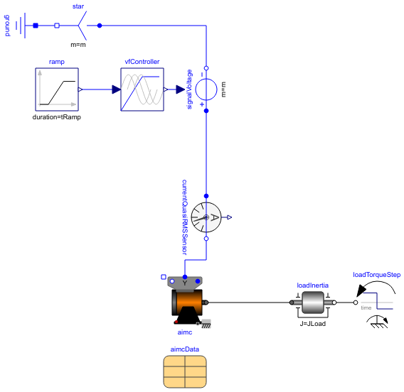
Diagram
Information
This information is part of the Modelica Standard Library maintained by the Modelica Association.
An ideal frequency inverter is modeled by using a VfController and a three-phase SignalVoltage. Frequency is raised by a ramp, causing the induction machine with squirrel cage to start, and accelerating inertias. At time tStep a load step is applied.
Simulate for 1.5 seconds and plot (versus time):
- currentQuasiRMSSensor.I: stator current RMS
- aimc.wMechanical: motor's speed
- aimc.tauElectrical: motor's torque
Parameters (8)
| VNominal |
Value: 100 Type: Voltage (V) Description: Nominal RMS voltage per phase |
|---|---|
| fNominal |
Value: aimcData.fsNominal Type: Frequency (Hz) Description: Nominal frequency |
| f |
Value: fNominal Type: Frequency (Hz) Description: Maximum operational frequency |
| tRamp |
Value: 1 Type: Time (s) Description: Frequency ramp |
| TLoad |
Value: 161.4 Type: Torque (N·m) Description: Nominal load torque |
| tStep |
Value: 1.2 Type: Time (s) Description: Time of load torque step |
| JLoad |
Value: 0.29 Type: Inertia (kg·m²) Description: Load's moment of inertia |
| aimcData |
Value: Type: IM_SquirrelCageData Description: Induction machine data |
Components (11)
| aimc |
Type: IM_SquirrelCage |
|
|---|---|---|
| currentQuasiRMSSensor |
Type: CurrentQuasiRMSSensor |
|
| ramp |
Type: Ramp |
|
| vfController |
Type: VfController |
|
| signalVoltage |
Type: SignalVoltage |
|
| star |
Type: Star |
|
| ground |
Type: Ground |
|
| loadInertia |
Type: Inertia |
|
| loadTorqueStep |
Type: TorqueStep |
|
| terminalBox |
Type: TerminalBox |
|
| aimcData |
Type: IM_SquirrelCageData Description: Induction machine data |