PolyphaseInductancePolyphase inductance |
|
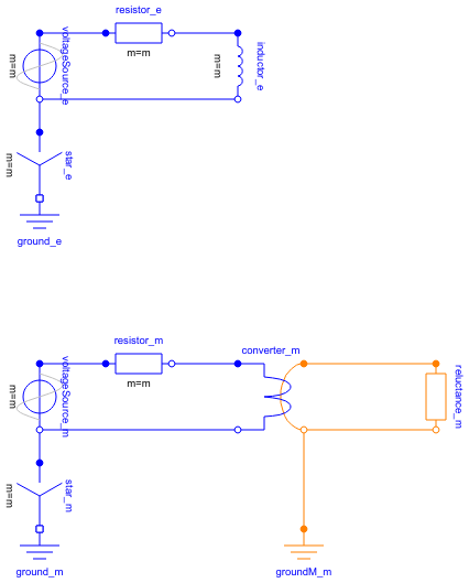
Diagram
Information
This information is part of the Modelica Standard Library maintained by the Modelica Association.
This example compares an electric polyphase inductor with an equivalent fundamental wave reluctance circuit.
The phase inductance L and the magnetic fundamental wave reluctance R_m are related by:
R_m = m * effectiveTurns^2 / 2 / L
The two currents
resistor_e.i[1]resistor_m.i[1]
show the same waveforms and thus prove the equivalence of the two different modelling approaches.
Parameters (7)
| m |
Value: 3 Type: Integer Description: Number of phases |
|---|---|
| f |
Value: 1 Type: Frequency (Hz) Description: Supply frequency |
| VRMS |
Value: 100 Type: Voltage (V) Description: RMS supply voltage |
| R |
Value: 0.1 Type: Resistance (Ω) Description: Leader cable resistance |
| effectiveTurns |
Value: 5 Type: Real Description: Effective number of turns |
| L |
Value: 1 Type: Inductance (H) Description: Load inductance |
| R_m |
Value: m * effectiveTurns ^ 2 / 2 / L Type: Reluctance (H⁻¹) Description: Equivalent magnetic reluctance |
Components (12)
| ground_e |
Type: Ground |
|
|---|---|---|
| ground_m |
Type: Ground |
|
| star_e |
Type: Star |
|
| star_m |
Type: Star |
|
| voltageSource_e |
Type: SineVoltage |
|
| voltageSource_m |
Type: SineVoltage |
|
| resistor_e |
Type: Resistor |
|
| resistor_m |
Type: Resistor |
|
| inductor_e |
Type: Inductor |
|
| converter_m | ||
| reluctance_m |
Type: Reluctance |
|
| groundM_m |
Type: Ground |