PolyphaseInductancePolyphase inductance |
|
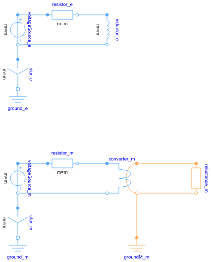
Diagram
Information
This information is part of the Modelica Standard Library maintained by the Modelica Association.
This example compares a quasi static electric polyphase inductor with an equivalent quasi static fundamental wave reluctance circuit.
The phase inductance L and the magnetic fundamental wave reluctance R_m are related by:
R_m = m * effectiveTurns^2 / 2 / L
The real parts
resistor_e.i[1].reresistor_m.i[1].re
and the imaginary parts
resistor_e.i[1].imresistor_m.i[1].im
of the two currents show the same result and thus prove the equivalence of the two different modelling approaches.
Parameters (7)
| m |
Value: 5 Type: Integer Description: Number of phases |
|---|---|
| f |
Value: 1 Type: Frequency (Hz) Description: Supply frequency |
| VRMS |
Value: 100 Type: Voltage (V) Description: RMS supply voltage |
| R |
Value: 1E-5 Type: Resistance (Ω) Description: Resistance |
| L |
Value: 1 Type: Inductance (H) Description: Load inductance |
| effectiveTurns |
Value: 5 Type: Real Description: Effective number of turns |
| R_m |
Value: m * effectiveTurns ^ 2 / 2 / L Type: Reluctance (H⁻¹) Description: Equivalent magnetic reluctance |
Outputs (2)
| Ie |
Default Value: resistor_e.i[1] Type: ComplexCurrent Description: Current of electric representation |
|---|---|
| Im |
Default Value: resistor_m.i[1] Type: ComplexCurrent Description: Current of magnetic representation |
Components (14)
| Ie |
Type: ComplexCurrent Description: Current of electric representation |
|
|---|---|---|
| Im |
Type: ComplexCurrent Description: Current of magnetic representation |
|
| ground_e |
Type: Ground |
|
| ground_m |
Type: Ground |
|
| star_e |
Type: Star |
|
| star_m |
Type: Star |
|
| voltageSource_e |
Type: VoltageSource |
|
| voltageSource_m |
Type: VoltageSource |
|
| resistor_e |
Type: Resistor |
|
| resistor_m |
Type: Resistor |
|
| inductor_e |
Type: Inductor |
|
| converter_m | ||
| reluctance_m |
Type: Reluctance |
|
| groundM_m |
Type: Ground |