DC to DC converters
General information about DC/DC converters can be found at the DC/DC converter concept
Extends from Modelica.Icons.Package (Icon for standard packages).
| Name | Description |
|---|---|
| Control components for DC to DC converters | |
| Step down chopper | |
| Step up chopper | |
| Bidirectional chopper | |
| H bridge (four quadrant converter) |
 Modelica.Electrical.PowerConverters.DCDC.ChopperStepDown
Step down chopper
This is a conventional step down chopper (buck converter) model. It consists of a transistor and free wheeling diode.
Extends from Icons.Converter (Converter icon), PowerConverters.Interfaces.DCDC.DCtwoPin1 (Positive and negative pins of side 1), PowerConverters.Interfaces.DCDC.DCtwoPin2 (Positive and negative pins of side 2), Modelica.Electrical.Analog.Interfaces.ConditionalHeatPort (Partial model to include a conditional HeatPort in order to describe the power loss via a thermal network), Interfaces.Enable.Enable1 (Partial model providing enable parameter and optional enable input for one firing signal).
| Name | Description |
|---|---|
| RonTransistor | Transistor closed resistance [Ohm] |
| GoffTransistor | Transistor opened conductance [S] |
| VkneeTransistor | Transistor threshold voltage [V] |
| RonDiode | Closed diode resistance [Ohm] |
| GoffDiode | Opened diode conductance [S] |
| VkneeDiode | Diode forward threshold voltage [V] |
| useHeatPort | = true, if heatPort is enabled |
| T | Fixed device temperature if useHeatPort = false [K] |
| Enable | |
| useConstantEnable | Disable boolean input and use constantEnable, if true |
| constantEnable | Constant enabling of firing signals |
| Name | Description |
|---|---|
| dc_p1 | Positive DC input |
| dc_n1 | Negative DC input |
| dc_p2 | Positive DC output |
| dc_n2 | Negative DC output |
| heatPort | Conditional heat port |
| enable | Enables fire and notFire |
| fire_p | Firing signal of positive potential transistor |
 Modelica.Electrical.PowerConverters.DCDC.ChopperStepUp
Step up chopper
This is a conventional step up chopper (boost converter) model. It consists of a transistor and free wheeling diode.
Extends from Icons.Converter (Converter icon), PowerConverters.Interfaces.DCDC.DCtwoPin1 (Positive and negative pins of side 1), PowerConverters.Interfaces.DCDC.DCtwoPin2 (Positive and negative pins of side 2), Modelica.Electrical.Analog.Interfaces.ConditionalHeatPort (Partial model to include a conditional HeatPort in order to describe the power loss via a thermal network), Interfaces.Enable.Enable1 (Partial model providing enable parameter and optional enable input for one firing signal).
| Name | Description |
|---|---|
| RonTransistor | Transistor closed resistance [Ohm] |
| GoffTransistor | Transistor opened conductance [S] |
| VkneeTransistor | Transistor threshold voltage [V] |
| RonDiode | Closed diode resistance [Ohm] |
| GoffDiode | Opened diode conductance [S] |
| VkneeDiode | Diode forward threshold voltage [V] |
| useHeatPort | = true, if heatPort is enabled |
| T | Fixed device temperature if useHeatPort = false [K] |
| Enable | |
| useConstantEnable | Disable boolean input and use constantEnable, if true |
| constantEnable | Constant enabling of firing signals |
| Name | Description |
|---|---|
| dc_p1 | Positive DC input |
| dc_n1 | Negative DC input |
| dc_p2 | Positive DC output |
| dc_n2 | Negative DC output |
| heatPort | Conditional heat port |
| enable | Enables fire and notFire |
| fire_p | Firing signal of positive potential transistor |
 Modelica.Electrical.PowerConverters.DCDC.ChopperBuckBoost
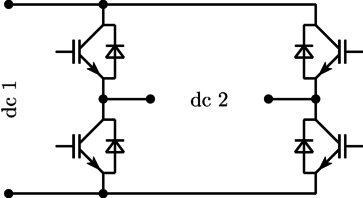
Bidirectional chopper
This is a bidirectional buck / boost - converter with 2 transistors and 2 freewheeling diodes.
Extends from Modelica.Electrical.PowerConverters.Interfaces.DCDC.DCtwoPin1 (Positive and negative pins of side 1), Modelica.Electrical.PowerConverters.Interfaces.DCDC.DCtwoPin2 (Positive and negative pins of side 2), Modelica.Electrical.Analog.Interfaces.ConditionalHeatPort (Partial model to include a conditional HeatPort in order to describe the power loss via a thermal network), Modelica.Electrical.PowerConverters.Interfaces.Enable.Enable2 (Partial model providing enable parameter and optional enable input for two firing signals).
| Name | Description |
|---|---|
| useHeatPort | = true, if heatPort is enabled |
| T | Fixed device temperature if useHeatPort = false [K] |
| RonTransistor | Transistor closed resistance [Ohm] |
| GoffTransistor | Transistor opened conductance [S] |
| VkneeTransistor | Transistor threshold voltage [V] |
| RonDiode | Diode closed resistance [Ohm] |
| GoffDiode | Diode opened conductance [S] |
| VkneeDiode | Diode threshold voltage [V] |
| Enable | |
| useConstantEnable | Disable boolean input and use constantEnable, if true |
| constantEnable | Constant enabling of firing signals |
| Name | Description |
|---|---|
| dc_p1 | Positive DC input |
| dc_n1 | Negative DC input |
| dc_p2 | Positive DC output |
| dc_n2 | Negative DC output |
| heatPort | Conditional heat port |
| enable | Enables fire and notFire |
| fire_p | Firing signal of positive potential transistor |
| fire_n | Firing signal of negative potential transistor |
 Modelica.Electrical.PowerConverters.DCDC.HBridge
H bridge (four quadrant converter)
The H bridge is a four quadrant DC/DC converter. It consists of two single-phase DC/AC converters which are controlled differently; see Fig. 1.
|
If the firing inputs fire_p and fire_n are inverse, the two legs are controlled symmetrically so that full positive or negative output voltage can be generated.
See examples DCDC.HBridge.
In the first version, the following signal connections were implementented:
Therefore the two fire signal had be supplied complentary to avoid a short circuit on the source.
In the enhanced version, the following signal connections are implementented:
Therefore a short circuit on the source is avoided intrinsically.
If both versions are provided with the same (complementary) fire signals, identical results are obtained. Additionally, two more switching states are possible: fire_p = fire_n = true (which means switching on both upper switches) and fire_p = fire_n = false (which means switching on both lower switches).
Extends from Icons.Converter (Converter icon), PowerConverters.Interfaces.DCDC.DCtwoPin1 (Positive and negative pins of side 1), PowerConverters.Interfaces.DCDC.DCtwoPin2 (Positive and negative pins of side 2), Modelica.Electrical.Analog.Interfaces.ConditionalHeatPort (Partial model to include a conditional HeatPort in order to describe the power loss via a thermal network), Interfaces.Enable.Enable2 (Partial model providing enable parameter and optional enable input for two firing signals).
| Name | Description |
|---|---|
| useHeatPort | = true, if heatPort is enabled |
| T | Fixed device temperature if useHeatPort = false [K] |
| RonTransistor | Transistor closed resistance [Ohm] |
| GoffTransistor | Transistor opened conductance [S] |
| VkneeTransistor | Transistor threshold voltage [V] |
| RonDiode | Diode closed resistance [Ohm] |
| GoffDiode | Diode opened conductance [S] |
| VkneeDiode | Diode threshold voltage [V] |
| Enable | |
| useConstantEnable | Disable boolean input and use constantEnable, if true |
| constantEnable | Constant enabling of firing signals |
| Name | Description |
|---|---|
| dc_p1 | Positive DC input |
| dc_n1 | Negative DC input |
| dc_p2 | Positive DC output |
| dc_n2 | Negative DC output |
| heatPort | Conditional heat port |
| enable | Enables fire and notFire |
| fire_p | Firing signal of positive potential transistor |
| fire_n | Firing signal of negative potential transistor |