Quasi static synchronous machines
Extends from Modelica.Icons.Package (Icon for standard packages).
| Name | Description |
|---|---|
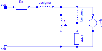
| Permanent magnet synchronous machine with optional damper cage | |
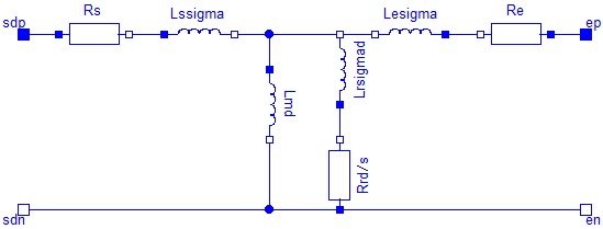
| Electrical excited synchronous machine with optional damper cage | |
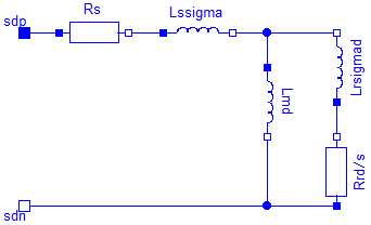
| Synchronous reluctance machine with optional damper cage |
 Modelica.Magnetic.QuasiStatic.FundamentalWave.BasicMachines.SynchronousMachines.SM_PermanentMagnet
Permanent magnet synchronous machine with optional damper cage
Resistances and stray inductances of the machine refer to an m phase stator. The symmetry of the stator and the supply are assumed. For rotor asymmetries can be taken into account by different resistances and stray inductances in the d- and q-axis. The machine models take the following loss effects into account:
SM_ElectricalExcited, SM_ReluctanceRotor, Magnetic.FundamentalWave.BasicMachines.SM_PermanentMagnet, Magnetic.FundamentalWave.BasicMachines.SM_ElectricalExcited, Magnetic.FundamentalWave.BasicMachines.SM_ReluctanceRotor,
Extends from BaseClasses.PartialBasicMachine (Partial model for quasi static multi phase machines).
| Name | Description |
|---|---|
| m | Number of stator phases |
| Jr | Rotor inertia [kg.m2] |
| useSupport | Enable / disable (=fixed stator) support |
| Js | Stator inertia [kg.m2] |
| useThermalPort | Enable / disable (=fixed temperatures) thermal port |
| p | Number of pole pairs (Integer) |
| fsNominal | Nominal frequency [Hz] |
| effectiveStatorTurns | Effective number of stator turns |
| VsOpenCircuit | Open circuit RMS voltage per phase @ fsNominal [V] |
| Operational temperatures | |
| TsOperational | Operational temperature of stator resistance [K] |
| TrOperational | Operational temperature of (optional) damper cage [K] |
| Initialization | |
| gammas | Angle of stator reference frame [rad] |
| gammar | Angle of stator reference frame [rad] |
| gamma | Electrical angle between stator and rotor [rad] |
| wMechanical | Mechanical angular velocity of rotor against stator [rad/s] |
| Nominal resistances and inductances | |
| TsRef | Reference temperature of stator resistance [K] |
| alpha20s | Temperature coefficient of stator resistance at 20 degC [1/K] |
| Lmd | Stator main field inductance per phase, d-axis [H] |
 | |
| Lmq | Stator main field inductance per phase, q-axis [H] |
| Damper cage | |
| useDamperCage | Enable/disable damper cage |
| Lrsigmad | Rotor leakage inductance, d-axis, w.r.t. stator side [H] |
| Lrsigmaq | Rotor leakage inductance, q-axis, w.r.t. stator side [H] |
| Rrd | Rotor resistance, d-axis, w.r.t. stator side [Ohm] |
| Rrq | Rotor resistance , q-axis, w.r.t. stator side [Ohm] |
| TrRef | Reference temperature of damper resistances in d- and q-axis [K] |
| alpha20r | Temperature coefficient of damper resistances in d- and q-axis [1/K] |
| Losses | |
| frictionParameters | Friction loss parameter record |
| statorCoreParameters | Stator core loss parameter record; all parameters refer to stator side |
| strayLoadParameters | Stray load loss parameter record |
| permanentMagnetLossParameters | Permanent magnet loss parameter record |
| Name | Description |
|---|---|
| flange | Shaft |
| support | Support at which the reaction torque is acting |
| plug_sp | Positive plug of stator |
| plug_sn | Negative plug of stator |
| internalSupport | |
| ir[2] | Damper cage currents |
 Modelica.Magnetic.QuasiStatic.FundamentalWave.BasicMachines.SynchronousMachines.SM_ElectricalExcited
Electrical excited synchronous machine with optional damper cage
Resistances and stray inductances of the machine refer to an m phase stator. The symmetry of the stator and the supply are assumed. For rotor asymmetries can be taken into account by different resistances and stray inductances in the d- and q-axis. The machine models take the following loss effects into account:
SM_PermanentMagnet, SM_ReluctanceRotor, Magnetic.FundamentalWave.BasicMachines.SM_PermanentMagnet, Magnetic.FundamentalWave.BasicMachines.SM_ElectricalExcited, Magnetic.FundamentalWave.BasicMachines.SM_ReluctanceRotor,
Extends from BaseClasses.PartialBasicMachine (Partial model for quasi static multi phase machines).
| Name | Description |
|---|---|
| m | Number of stator phases |
| Jr | Rotor inertia [kg.m2] |
| useSupport | Enable / disable (=fixed stator) support |
| Js | Stator inertia [kg.m2] |
| useThermalPort | Enable / disable (=fixed temperatures) thermal port |
| p | Number of pole pairs (Integer) |
| fsNominal | Nominal frequency [Hz] |
| effectiveStatorTurns | Effective number of stator turns |
| Operational temperatures | |
| TsOperational | Operational temperature of stator resistance [K] |
| TrOperational | Operational temperature of (optional) damper cage [K] |
| TeOperational | Operational excitation temperature [K] |
| Initialization | |
| gammas | Angle of stator reference frame [rad] |
| gammar | Angle of stator reference frame [rad] |
| gamma | Electrical angle between stator and rotor [rad] |
| wMechanical | Mechanical angular velocity of rotor against stator [rad/s] |
| Nominal resistances and inductances | |
| TsRef | Reference temperature of stator resistance [K] |
| alpha20s | Temperature coefficient of stator resistance at 20 degC [1/K] |
| Lmd | Stator main field inductance per phase, d-axis [H] |
 | |
| Lmq | Stator main field inductance per phase, q-axis [H] |
| DamperCage | |
| useDamperCage | Enable/disable damper cage |
| Lrsigmad | Rotor leakage inductance, d-axis, w.r.t. stator side [H] |
| Lrsigmaq | Rotor leakage inductance, q-axis, w.r.t. stator side [H] |
| Rrd | Rotor resistance, d-axis, w.r.t. stator side [Ohm] |
| Rrq | Rotor resistance , q-axis, w.r.t. stator side [Ohm] |
| TrRef | Reference temperature of damper resistances in d- and q-axis [K] |
| alpha20r | Temperature coefficient of damper resistances in d- and q-axis [1/K] |
| Losses | |
| frictionParameters | Friction loss parameter record |
| statorCoreParameters | Stator core loss parameter record; all parameters refer to stator side |
| strayLoadParameters | Stray load loss parameter record |
| brushParameters | Brush loss parameter record |
| Excitation | |
| VsNominal | Nominal stator voltage [V] |
| IeOpenCircuit | Open circuit excitation current @ nominal voltage and frequency [A] |
| Re | Warm excitation resistance [Ohm] |
| TeRef | Reference temperature of excitation resistance [K] |
| alpha20e | Temperature coefficient of excitation resistance [1/K] |
| Name | Description |
|---|---|
| flange | Shaft |
| support | Support at which the reaction torque is acting |
| plug_sp | Positive plug of stator |
| plug_sn | Negative plug of stator |
| internalSupport | |
| ir[2] | Damper cage currents |
| pin_ep | Positive pin of excitation |
| pin_en | Negative pin of excitation |
 Modelica.Magnetic.QuasiStatic.FundamentalWave.BasicMachines.SynchronousMachines.SM_ReluctanceRotor
Synchronous reluctance machine with optional damper cage
Resistances and stray inductances of the machine refer to an m phase stator. The symmetry of the stator and the supply are assumed. For rotor asymmetries can be taken into account by different resistances and stray inductances in the d- and q-axis. The machine models take the following loss effects into account:
SM_PermanentMagnet, SM_ElectricalExcited, Magnetic.FundamentalWave.BasicMachines.SM_PermanentMagnet, Magnetic.FundamentalWave.BasicMachines.SM_ElectricalExcited, Magnetic.FundamentalWave.BasicMachines.SM_ReluctanceRotor,
Extends from BaseClasses.PartialBasicMachine (Partial model for quasi static multi phase machines).
| Name | Description |
|---|---|
| m | Number of stator phases |
| Jr | Rotor inertia [kg.m2] |
| useSupport | Enable / disable (=fixed stator) support |
| Js | Stator inertia [kg.m2] |
| useThermalPort | Enable / disable (=fixed temperatures) thermal port |
| p | Number of pole pairs (Integer) |
| fsNominal | Nominal frequency [Hz] |
| effectiveStatorTurns | Effective number of stator turns |
| Operational temperatures | |
| TsOperational | Operational temperature of stator resistance [K] |
| TrOperational | Operational temperature of (optional) damper cage [K] |
| Initialization | |
| gammas | Angle of stator reference frame [rad] |
| gammar | Angle of stator reference frame [rad] |
| gamma | Electrical angle between stator and rotor [rad] |
| wMechanical | Mechanical angular velocity of rotor against stator [rad/s] |
| Nominal resistances and inductances | |
| TsRef | Reference temperature of stator resistance [K] |
| alpha20s | Temperature coefficient of stator resistance at 20 degC [1/K] |
| Lmd | Stator main field inductance per phase, d-axis [H] |
 | |
| Lmq | Stator main field inductance per phase, q-axis [H] |
| DamperCage | |
| useDamperCage | Enable/disable damper cage |
| Lrsigmad | Rotor leakage inductance, d-axis, w.r.t. stator side [H] |
| Lrsigmaq | Rotor leakage inductance, q-axis, w.r.t. stator side [H] |
| Rrd | Rotor resistance, d-axis, w.r.t. stator side [Ohm] |
| Rrq | Rotor resistance , q-axis, w.r.t. stator side [Ohm] |
| TrRef | Reference temperature of damper resistances in d- and q-axis [K] |
| alpha20r | Temperature coefficient of damper resistances in d- and q-axis [1/K] |
| Losses | |
| frictionParameters | Friction loss parameter record |
| statorCoreParameters | Stator core loss parameter record; all parameters refer to stator side |
| strayLoadParameters | Stray load loss parameter record |
| Name | Description |
|---|---|
| flange | Shaft |
| support | Support at which the reaction torque is acting |
| plug_sp | Positive plug of stator |
| plug_sn | Negative plug of stator |
| internalSupport | |
| ir[2] | Damper cage currents |