PositionControlledDCPMPosition controlled DC PM drive with H-bridge from battery |
|
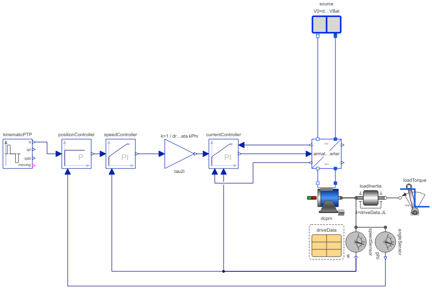
Diagram
Information
This information is part of the Modelica Standard Library maintained by the Modelica Association.
This model demonstrates how a position controller for a speed controlled DC PM drive works.
The inner current controller is parameterized according to the absolute optimum. The middle control loop is formed by the speed controller which is parameterized according to the symmetrical optimum. The outer control loop is formed by the position controller which is parameterized to avoid an overshot in the position.
At time=0.2 s the kinematicPTP starts to prescribe the reference position with limited speed and limited acceleration. At time=2.3 s a load torque step is applied, causing to drive to slightly leave the end position until the position controller brings the drive back to the desired position.
Further reading: Tutorial at the Modelica Conference 2017
Parameters (1)
| driveData |
Value: Type: DriveDataDCPM |
|---|
Components (13)
| driveData |
Type: DriveDataDCPM |
|
|---|---|---|
| loadInertia |
Type: Inertia |
|
| speedSensor |
Type: SpeedSensor |
|
| dcpm |
Type: DC_PermanentMagnet |
|
| armatureInverter |
Type: DcdcInverter |
|
| source |
Type: Battery |
|
| currentController |
Type: LimitedPI |
|
| tau2i |
Type: Gain |
|
| loadTorque |
Type: TorqueStep |
|
| speedController |
Type: LimitedPI |
|
| positionController |
Type: LimitedPI |
|
| angleSensor |
Type: AngleSensor |
|
| kinematicPTP |
Type: KinematicPTP2 |