RectifierB6 diode bridge |
|
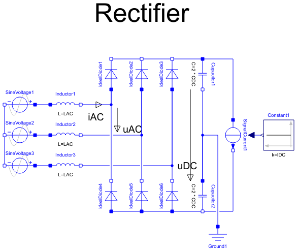
Diagram
Information
This information is part of the Modelica Standard Library maintained by the Modelica Association.
The rectifier example shows a B6 diode bridge fed by a three-phase sinusoidal voltage, loaded by a DC current. DC capacitors start at ideal no-load voltage, thus making easier initial transient.
Simulate until T=0.1 s. Plot in separate windows:
uDC ... DC-voltage
iAC ... AC-currents 1..3
uAC ... AC-voltages 1..3 (distorted)
Try different load currents iDC = 0..approximately 500 A. You may watch losses (of the whole diode bridge) trying different diode parameters.
Parameters (8)
| VAC |
Value: 400 Type: Voltage (V) Description: RMS line-to-line |
|---|---|
| f |
Value: 50 Type: Frequency (Hz) Description: Line frequency |
| LAC |
Value: 60E-6 Type: Inductance (H) Description: Line inductor |
| Ron |
Value: 1E-3 Type: Resistance (Ω) Description: Diode forward resistance |
| Goff |
Value: 1E-3 Type: Conductance (S) Description: Diode backward conductance |
| Vknee |
Value: 2 Type: Voltage (V) Description: Diode threshold voltage |
| CDC |
Value: 15E-3 Type: Capacitance (F) Description: DC capacitance |
| IDC |
Value: 500 Type: Current (A) Description: Load current |
Outputs (4)
| uDC |
Type: Voltage (V) |
|---|---|
| iAC |
Type: Current[3] (A) |
| uAC |
Type: Voltage[3] (V) |
| Losses |
Type: Power (W) |
Components (17)
| SineVoltage1 |
Type: SineVoltage |
|
|---|---|---|
| SineVoltage2 |
Type: SineVoltage |
|
| SineVoltage3 |
Type: SineVoltage |
|
| Inductor1 |
Type: Inductor |
|
| Inductor2 |
Type: Inductor |
|
| Inductor3 |
Type: Inductor |
|
| IdealDiode1 |
Type: IdealDiode |
|
| IdealDiode2 |
Type: IdealDiode |
|
| IdealDiode3 |
Type: IdealDiode |
|
| IdealDiode4 |
Type: IdealDiode |
|
| IdealDiode5 |
Type: IdealDiode |
|
| IdealDiode6 |
Type: IdealDiode |
|
| Capacitor1 |
Type: Capacitor |
|
| Capacitor2 |
Type: Capacitor |
|
| Ground1 |
Type: Ground |
|
| SignalCurrent1 |
Type: SignalCurrent |
|
| Constant1 |
Type: Constant |