IncompressibleFluidNetworkMulti-way connections of pipes and incompressible medium model |
|
Diagram
Information
This information is part of the Modelica Standard Library maintained by the Modelica Association.
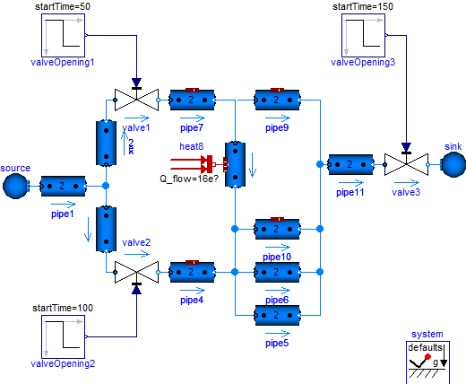
This example demonstrates two aspects: the treatment of multi-way connections and the usage of an incompressible medium model.
Eleven pipe models with nNodes=2 each introduce 22 temperature states and 22 pressure states. When configuring pipeModelStructure=a_v_b, the flow models at the pipe ports constitute algebraic loops for the pressures. A common work-around is to introduce "mixing volumes" in critical connections.
Here the problem is treated alternatively with the default pipeModelStructure=av_vb of the DynamicPipe model. Each pipe exposes the states of the outer fluid segments to the respective fluid ports. Consequently the pressures of all connected pipe segments get lumped together into one mass balance spanning the whole connection set. Overall this treatment as high-index DAE results in the reduction to 9 pressure states, preventing algebraic loops in connections. This can be studied with a rigorous medium model like StandardWaterOnePhase.
The pressure dynamics completely disappears with an incompressible medium model, like the used Glycol47. It appears reasonable to assume steady-state mass balances in this case (see parameter systemMassDynamics used in system.massDynamics, tab Assumptions).
Note that with the stream concept in the fluid ports, the energy and substance balances of the connected pipe segments remain independent from each other, despite of pressures being lumped together. The following simulation results can be observed:
- The simulation starts with system.T_ambient as initial temperature in all pipes. The temperatures upstream or bypassing pipe8 are approaching the value of 26.85 degC from the source, including also pipe9. The temperatures downstream of pipe8 take a higher value, depending on the mixing with heated fluid, see e.g. pipe10.
- After 50s valve1 fully closes. This causes flow reversal in pipe8. Now heated fluid flows from pipe8 to pipe9. Note that the temperature of the connected pipe7 remains unchanged as there is no flow into pipe7. The temperature of pipe10 cools down to the source temperature.
- After 100s valve2 closes half way, which affects mass flow rates and temperatures.
- After 150s valve5 closes half way, which affects mass flow rates and temperatures.
The fluid temperatures in the pipes of interest are exposed through heatPorts.

Parameters (2)
| pipeModelStructure |
Value: Modelica.Fluid.Types.ModelStructure.av_vb Type: ModelStructure Description: Model structure in distributed pipe model |
|---|---|
| systemMassDynamics |
Value: if Medium.singleState then Dynamics.SteadyState else Dynamics.SteadyStateInitial Type: Dynamics Description: Formulation of mass balances |
Components (21)
| source |
Type: Boundary_pT |
|
|---|---|---|
| pipe1 |
Type: DynamicPipe |
|
| pipe2 |
Type: DynamicPipe |
|
| pipe3 |
Type: DynamicPipe |
|
| pipe4 |
Type: DynamicPipe |
|
| pipe6 |
Type: DynamicPipe |
|
| valve1 |
Type: ValveIncompressible |
|
| valve2 |
Type: ValveIncompressible |
|
| pipe7 |
Type: DynamicPipe |
|
| valve3 |
Type: ValveIncompressible |
|
| sink |
Type: Boundary_pT |
|
| system |
Type: System |
|
| valveOpening1 |
Type: Step |
|
| valveOpening2 |
Type: Step |
|
| valveOpening3 |
Type: Step |
|
| pipe8 |
Type: DynamicPipe |
|
| pipe9 |
Type: DynamicPipe |
|
| pipe10 |
Type: DynamicPipe |
|
| pipe5 |
Type: DynamicPipe |
|
| heat8 | ||
| pipe11 |
Type: DynamicPipe |
