ThreePhaseTransformerWithRectifierThree-phase transformer (including hysteresis effect) with rectifier |
|
Diagram
Information
This information is part of the Modelica Standard Library maintained by the Modelica Association.
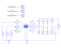
This is a model of a three-phase transformer and rectifier unit using the Transformer3PhaseYyWithHysteresis model. Use the following simulation settings:
- Stop time: 0.2 s
- Number of intervals: 5000
- Tolerance: 1e-6
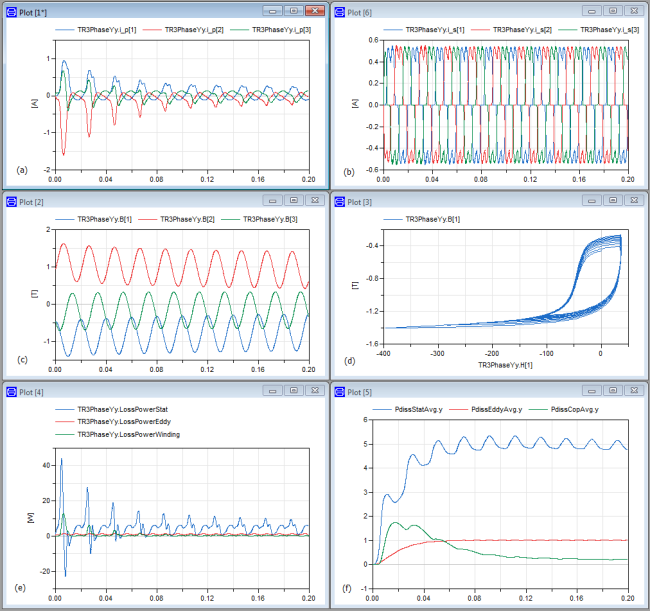
An example simulation shows the transformer inrush currents due to an initially magnetized transformer core.

|
Components (27)
| ground1 |
Type: Ground |
|
|---|---|---|
| ground2 |
Type: Ground |
|
| vSource1 |
Type: SineVoltage |
|
| transformer | ||
| vSource2 |
Type: SineVoltage |
|
| vSource3 |
Type: SineVoltage |
|
| resistor1 |
Type: Resistor |
|
| resistor2 |
Type: Resistor |
|
| resistor3 |
Type: Resistor |
|
| diode1 |
Type: IdealDiode |
|
| diode2 |
Type: IdealDiode |
|
| resistorL |
Type: Resistor |
|
| diode3 |
Type: IdealDiode |
|
| diode4 |
Type: IdealDiode |
|
| diode5 |
Type: IdealDiode |
|
| diode6 |
Type: IdealDiode |
|
| capacitor1 |
Type: Capacitor |
|
| inductor1 |
Type: Inductor |
|
| inductor2 |
Type: Inductor |
|
| inductor3 |
Type: Inductor |
|
| capacitor2 |
Type: Capacitor |
|
| rExp1 |
Type: RealExpression |
|
| rExp2 |
Type: RealExpression |
|
| rExp3 |
Type: RealExpression |
|
| pdissStatAvg |
Type: Filter Description: Approx. average static hysteresis losses |
|
| pdissEddyAvg |
Type: Filter Description: Approx. average eddy current losses |
|
| pdissCopAvg |
Type: Filter Description: Approx. average copper losses |
