| Name | Description |
|---|---|
AbsoluteSensor | Obsolete model. Use instead Modelica.Mechanics.MultiBody.Sensors.AbsoluteSensor |
CutForceAndTorque | Obsolete model. Use instead Modelica.Mechanics.MultiBody.Sensors.CutForceAndTorque |
RelativeSensor | Obsolete model. Use instead Modelica.Mechanics.MultiBody.Sensors.RelativeSensor |
Absolute kinematic quantities of frame_a are computed and provided at the output signal connector y in packed format in the order
For example, if parameters get_v and get_w are true and all other get_XXX parameters are false, then y contains 6 elements:
 y[1:3] = absolute velocity
 y[4:6] = absolute angular velocity
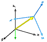
In the following figure the animation of an AbsoluteSensor component is shown. The light blue coordinate system is frame_a and the yellow arrow is the animated sensor.
If frame_resolve is connected to another frame, then the provided absolute kinematic vectors are resolved in this frame. If frame_resolve is not connected then the coordinate system in which the relative quantities are resolved is defined by parameter resolveInFrame_a. If this parameter is true, then the provided kinematic vectors are resolved in frame_a of this component. Otherwise, the kinematic vectors are resolved in the world frame. For example, if frame_resolve is not connected and if resolveInFrame_a = false, and get_v = true, then
y = der(frame_a.r) // resolved in world frame
is returned, i.e., the derivative of the distance frame_a.r_0 from the origin of the world frame to the origin of frame_a, resolved in the world frame.
Note, the cut-force and the cut-torque in frame_resolve are always zero, whether frame_resolve is connected or not.
If get_angles = true, the 3 angles to rotate the world frame into frame_a along the axes defined by parameter sequence are returned. For example, if sequence = {3,1,2} then the world frame is rotated around angles[1] along the z-axis, afterwards it is rotated around angles[2] along the x-axis, and finally it is rotated around angles[3] along the y-axis and is then identical to frame_a. The 3 angles are returned in the range
-p <= angles[i] <= p
There are two solutions for "angles[1]" in this range. Via parameter guessAngle1 (default = 0) the returned solution is selected such that |angles[1] - guessAngle1| is minimal. The transformation matrix between the world frame and frame_a may be in a singular configuration with respect to "sequence", i.e., there is an infinite number of angle values leading to the same transformation matrix. In this case, the returned solution is selected by setting angles[1] = guessAngle1. Then angles[2] and angles[3] can be uniquely determined in the above range.
Note, that parameter sequence has the restriction that only values 1,2,3 can be used and that sequence[1] ≠ sequence[2] and sequence[2] ≠ sequence[3]. Often used values are:
  sequence = {1,2,3}  // Cardan angle sequence
           = {3,1,3}  // Euler angle sequence
           = {3,2,1}  // Tait-Bryan angle sequence
Exact definition of the returned quantities:
| frame_resolve is | resolveInFrame_a = | vector is resolved in |
|---|---|---|
| connected | true | frame_resolve |
| connected | false | frame_resolve |
| not connected | true | frame_a |
| not connected | false | world frame |
Extends from Modelica.Mechanics.MultiBody.Interfaces.PartialAbsoluteSensor (Base model to measure an absolute frame variable) and ObsoleteModelica3.Icons.ObsoleteModel (Icon for an obsolete model (use only for this case)).
| Type | Name | Default | Description |
|---|---|---|---|
final Integer | n_out | 3 * ((if get_r_abs then 1 else 0) + (if get_v_abs then 1 else 0) + (if get_a_abs then 1 else 0) + (if get_angles then 1 else 0) + (if get_w_abs then 1 else 0) + (if get_z_abs then 1 else 0)) | Number of output signals |
Boolean | animation | true | = true, if animation shall be enabled (show arrow) |
Boolean | resolveInFrame_a | false | = true, if vectors are resolved in frame_a, otherwise in the world frame (if connector frame_resolve is connected, vectors are resolved in frame_resolve) |
Boolean | get_r_abs | true | = true, to measure the position vector from the origin of the world frame to the origin of frame_a in [m] |
Boolean | get_v_abs | false | = true, to measure the absolute velocity of the origin of frame_a in [m/s] |
Boolean | get_a_abs | false | = true, to measure the absolute acceleration of the origin of frame_a in [m/s^2] |
Boolean | get_angles | false | = true, to measure the 3 rotation angles to rotate the world frame into frame_a along the axes defined in 'sequence' below in [rad] |
Boolean | get_w_abs | false | = true, to measure the absolute angular velocity of frame_a in [rad/s] |
Boolean | get_z_abs | false | = true, to measure the absolute angular acceleration to frame_a in [rad/s^2] |
RotationSequence | sequence[3] | {1, 2, 3} | Angles are returned to rotate world frame around axes sequence[1], sequence[2] and finally sequence[3] into frame_a |
Angle | guessAngle1 | 0 | Select angles[1] such that abs(angles[1] - guessAngle1) is a minimum |
| Type | Name | Description |
|---|---|---|
Frame_a | frame_a | Coordinate system from which absolute quantities are provided as output signals |
output RealOutput | y[n_out] | Measured data as signal vector |
Frame_resolve | frame_resolve | If connected, the output signals are resolved in this frame |
Relative kinematic quantities between frame_a and frame_b are determined and provided at the output signal connector y in packed format in the order
For example, if parameters get_v_rel and get_w_rel are true and all other get_XXX parameters are false, then y contains 6 elements:
 y = relative velocity
 y = relative angular velocity
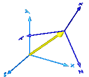
In the following figure the animation of a RelativeSensor component is shown. The light blue coordinate system is frame_a, the dark blue coordinate system is frame_b, and the yellow arrow is the animated sensor.
If parameter resolveInFrame_a = true, then the provided relative kinematic vectors of frame_b with respect to frame_a are resolved before differentiation in frame_a. If this parameter is false, the relative kinematic vectors are resolved before differentiation in frame_b. If frame_resolve is connected to another frame, then the kinematic vector as defined above and/or its required derivatives are resolved in frame_resolve. Note, derivatives of relative kinematic quantities are always performed with respect to frame_a (resolveInFrame_a = true) or with respect to frame_b (resolveInFrame_a = false). The resulting vector is then resolved in frame_resolve, if this connector is connected.
For example, if frame_resolve is not connected and if resolveInFrame_a = false, and get_v = true, then
  y = v_rel
    = der(r_rel)
is returned (r_rel = resolve2(frame_b.R, frame_b.r_0 - frame_a.r0)), i.e., the derivative of the relative distance from frame_a to frame_b, resolved in frame_b. If frame_resolve is connected, then
  y = v_rel
    = resolve2(frame_resolve.R, der(r_rel))
is returned, i.e., the previous relative velocity vector is additionally resolved in frame_resolve.
Note, the cut-force and the cut-torque in frame_resolve are always zero, whether frame_resolve is connected or not.
If get_angles = true, the 3 angles to rotate frame_a into frame_b along the axes defined by parameter sequence are returned. For example, if sequence = {3,1,2} then frame_a is rotated around angles[1] along the z-axis, afterwards it is rotated around angles[2] along the x-axis, and finally it is rotated around angles[3] along the y-axis and is then identical to frame_b. The 3 angles are returned in the range
-p <= angles[i] <= p
There are two solutions for "angles[1]" in this range. Via parameter guessAngle1 (default = 0) the returned solution is selected such that |angles[1] - guessAngle1| is minimal. The relative transformation matrix between frame_a and frame_b may be in a singular configuration with respect to "sequence", i.e., there is an infinite number of angle values leading to the same relative transformation matrix. In this case, the returned solution is selected by setting angles[1] = guessAngle1. Then angles[2] and angles[3] can be uniquely determined in the above range.
Note, that parameter sequence has the restriction that only values 1,2,3 can be used and that sequence[1] ≠ sequence[2] and sequence[2] ≠ sequence[3]. Often used values are:
  sequence = {1,2,3}  // Cardan angle sequence
           = {3,1,3}  // Euler angle sequence
           = {3,2,1}  // Tait-Bryan angle sequence
Exact definition of the returned quantities (r_rel_ab, R_rel_ab, w_rel_ab are defined below the enumeration):
using the auxiliary quantities
and resolved in the following frame
| frame_resolve is | resolveInFrame_a = | vector is resolved in |
|---|---|---|
| connected | true | frame_resolve |
| connected | false | frame_resolve |
| not connected | true | frame_a |
| not connected | false | frame_b |
Extends from Modelica.Mechanics.MultiBody.Interfaces.PartialRelativeSensor (Base model to measure a relative variable between two frames) and ObsoleteModelica3.Icons.ObsoleteModel (Icon for an obsolete model (use only for this case)).
| Type | Name | Default | Description |
|---|---|---|---|
final Integer | n_out | 3 * ((if get_r_rel then 1 else 0) + (if get_v_rel then 1 else 0) + (if get_a_rel then 1 else 0) + (if get_angles then 1 else 0) + (if get_w_rel then 1 else 0) + (if get_z_rel then 1 else 0)) | Number of output signals |
Boolean | animation | true | = true, if animation shall be enabled (show arrow) |
Boolean | resolveInFrame_a | true | = true, if relative vectors from frame_a to frame_b are resolved before differentiation in frame_a, otherwise in frame_b. If frame_resolve is connected, the vector and its derivatives are resolved in frame_resolve |
Boolean | get_r_rel | true | = true, to measure the relative position vector from the origin of frame_a to the origin of frame_b in [m] |
Boolean | get_v_rel | false | = true, to measure the relative velocity of the origin of frame_b with respect to frame_a in [m/s] |
Boolean | get_a_rel | false | = true, to measure the relative acceleration of the origin of frame_b with respect to frame_a in [m/s^2] |
Boolean | get_angles | false | = true, to measure the 3 rotation angles to rotate frame_a into frame_b along the axes defined in 'sequence' below in [rad] |
Boolean | get_w_rel | false | = true, to measure the relative angular velocity of frame_b with respect to frame_a in [rad/s] |
Boolean | get_z_rel | false | = true, to measure the relative angular acceleration of frame_b with respect to frame_a in [rad/s^2] |
RotationSequence | sequence[3] | {1, 2, 3} | Angles are returned to rotate frame_a around axes sequence[1], sequence[2] and finally sequence[3] into frame_b |
Angle | guessAngle1 | 0 | Select angles[1] such that abs(angles[1] - guessAngle1) is a minimum |
| Type | Name | Description |
|---|---|---|
Frame_a | frame_a | Coordinate system a |
Frame_b | frame_b | Coordinate system b |
output RealOutput | y[n_out] | Measured data as signal vector |
Frame_resolve | frame_resolve | If connected, the output signals are resolved in this frame |
The cut-force and cut-torque acting at the component to which frame_b is connected are determined and provided at the output signal connector load:
  load[1:3] = frame_a.f;
  load[4:6] = frame_a.t;
If parameter positiveSign = false, the negative cut-force and negative cut-torque is provided (= frame_b.f and frame_b.t). If frame_resolve is connected to another frame, then the cut-force and cut-torque are resolved in frame_resolve. If frame_resolve is not connected then the coordinate system in which the cut-force and cut-torque is resolved is defined by parameter resolveInFrame_a. If this parameter is true, then the cut-force and cut-torque is resolved in frame_a, otherwise it is resolved in the world frame.
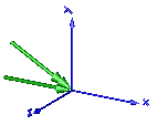
In the following figure the animation of a CutForceAndTorque sensor is shown. The dark blue coordinate system is frame_b, and the green arrows are the cut force and the cut torque, respectively, acting at frame_b and with negative sign at frame_a.
Extends from ObsoleteModelica3.Mechanics.MultiBody.Interfaces.PartialCutForceSensor (Obsolete model. Use instead a model from Modelica.Mechanics.MultiBody.Sensors).
| Type | Name | Default | Description |
|---|---|---|---|
Boolean | animation | true | = true, if animation shall be enabled (show force and torque arrow) |
Boolean | positiveSign | true | = true, if force and torque with positive sign is returned (= frame_a.f/.t), otherwise with negative sign (= frame_b.f/.t) |
Boolean | resolveInFrame_a | true | = true, if force and torque are resolved in frame_a/frame_b, otherwise in the world frame (if connector frame_resolve is connected, the force/torque is resolved in frame_resolve) |
| Type | Name | Description |
|---|---|---|
Frame_a | frame_a | Coordinate system with one cut-force and cut-torque |
Frame_b | frame_b | Coordinate system with one cut-force and cut-torque |
Frame_resolve | frame_resolve | If connected, the output signals are resolved in this frame (cut-force/-torque are set to zero) |
output RealOutput | load[6] | Cut force and cut torque resolved in frame_a/frame_b or in frame_resolved, if connected |
Generated 2018-12-12 12:17:45 EST by MapleSim.