AD_DA_conversionConversion circuit |
|
Diagram
Information
This information is part of the Modelica Standard Library maintained by the Modelica Association.
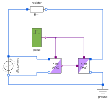
The simple converter circuit converts an analog sine signal into a N-bit (by default a 4 bit) logic signal, which is converted backward into an analog signal.
- Simulate for 0.2 s.
Compare the input voltage (aD_Converter.p.v) with the output voltage (dA_Converter.p.v). By changing N the influence of the digital signal width can be studied. Otherwise the trigger frequency pulse.period can be changed to see its influence.
Parameters (1)
| N |
Value: 7 Type: Integer Description: Digital signal width |
|---|
Components (6)
| aD_Converter |
Type: AD_Converter |
|
|---|---|---|
| pulse |
Type: Pulse |
|
| dA_Converter |
Type: DA_Converter |
|
| ground |
Type: Ground |
|
| sineVoltage |
Type: SineVoltage |
|
| resistor |
Type: Resistor |