HeatingPNP_NORGateHeating PNP NOR Gate |
|
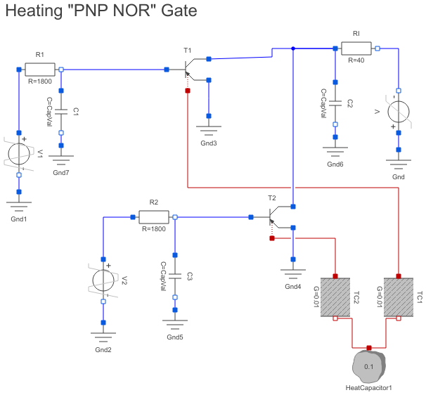
Diagram
Information
This information is part of the Modelica Standard Library maintained by the Modelica Association.
The heating "PNP NOR" gate shows a heat flow always if a transistor is conducting.
Simulate until T=200 s. Plot V1.v and V2.v and C2.v to see the NOR-functionality. High potential is -6V which means logic "true". Low potential is 0V which means logic "false".
To see which transistor is conducting one can have a look at the temperatures T1.heatPort.T and T2.heatPort.T and the heat flows T1.heatPort.Q_flow and T2.heatPort.Q_flow of the heatports of the transistors T1 and T2.
They are different from zero if the transistor is conducting.
Parameters (2)
| CapVal |
Value: 0 Type: Capacitance (F) |
|---|---|
| tauVal |
Value: 0 Type: Time (s) |
Components (22)
| HeatCapacitor1 |
Type: HeatCapacitor |
|
|---|---|---|
| TC1 |
Type: ThermalConductor |
|
| TC2 |
Type: ThermalConductor |
|
| V |
Type: RampVoltage |
|
| V1 |
Type: TrapezoidVoltage |
|
| V2 |
Type: TrapezoidVoltage |
|
| R1 |
Type: Resistor |
|
| R2 |
Type: Resistor |
|
| RI |
Type: Resistor |
|
| Gnd |
Type: Ground |
|
| Gnd2 |
Type: Ground |
|
| Gnd3 |
Type: Ground |
|
| Gnd4 |
Type: Ground |
|
| C1 |
Type: Capacitor |
|
| C2 |
Type: Capacitor |
|
| C3 |
Type: Capacitor |
|
| Gnd5 |
Type: Ground |
|
| Gnd6 |
Type: Ground |
|
| Gnd7 |
Type: Ground |
|
| T1 |
Type: HeatingPNP |
|
| T2 |
Type: HeatingPNP |
|
| Gnd1 |
Type: Ground |