HighPassHigh-pass filter |
|
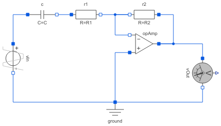
Diagram
Information
This information is part of the Modelica Standard Library maintained by the Modelica Association.
This is a (inverting) high pass filter. Resistance R1 can be chosen, resistance R2 is defined by the desired amplification k, capacitance C is defined by the desired cut-off frequency.
The example is taken from: U. Tietze and C. Schenk, Halbleiter-Schaltungstechnik (German), 11th edition, Springer 1999, Chapter 13.3
Parameters (9)
| Vps |
Value: +15 Type: Voltage (V) Description: Positive supply |
|---|---|
| Vns |
Value: -15 Type: Voltage (V) Description: Negative supply |
| Vin |
Value: 5 Type: Voltage (V) Description: Amplitude of input voltage |
| f |
Value: 10 Type: Frequency (Hz) Description: Frequency of input voltage |
| k |
Value: 1 Type: Real Description: Desired amplification |
| R1 |
Value: 1000 Type: Resistance (Ω) Description: Arbitrary resistance |
| R2 |
Value: k * R1 Type: Resistance (Ω) Description: Calculated resistance to reach k |
| fG |
Value: f / 10 Type: Frequency (Hz) Description: Limiting frequency, as an example coupled to f |
| C |
Value: 1 / (2 * pi * fG * R1) Type: Capacitance (F) Description: Calculated capacitance to reach fG |
Components (7)
| opAmp |
Type: IdealizedOpAmpLimted |
|
|---|---|---|
| ground |
Type: Ground |
|
| vIn |
Type: TrapezoidVoltage |
|
| vOut |
Type: VoltageSensor |
|
| r1 |
Type: Resistor |
|
| r2 |
Type: Resistor |
|
| c |
Type: Capacitor |