SpeedControlledDCPMSpeed controlled DC PM drive with H-bridge from battery |
|
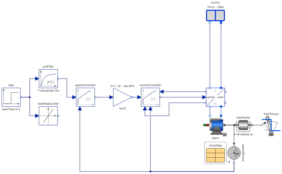
Diagram
Information
This information is part of the Modelica Standard Library maintained by the Modelica Association.
This model demonstrates how a speed controller for a current controlled DC PM drive works.
The inner current controller is parameterized according to the absolute optimum. The outer control loop is formed by the speed controller which is parameterized according to the symmetrical optimum.
At time=0.2 s a reference speed step is applied, causing the drive to accelerate to the desired speed. At time=0.8 s a load torque step is applied, causing to drive to decelerate until the speed controller brings the drive back to the desired speed.
You may try a slewRateLimiter instead of the prefilter to limit the speed rise i.e. the torque.
Further reading: Tutorial at the Modelica Conference 2017
Parameters (1)
| driveData |
Value: Type: DriveDataDCPM |
|---|
Components (13)
| driveData |
Type: DriveDataDCPM |
|
|---|---|---|
| loadInertia |
Type: Inertia |
|
| speedSensor |
Type: SpeedSensor |
|
| dcpm |
Type: DC_PermanentMagnet |
|
| armatureInverter |
Type: DcdcInverter |
|
| source |
Type: Battery |
|
| currentController |
Type: LimitedPI |
|
| tau2i |
Type: Gain |
|
| loadTorque |
Type: TorqueStep |
|
| speedController |
Type: LimitedPI |
|
| preFilter |
Type: FirstOrder |
|
| step |
Type: Step |
|
| slewRateLimiter |
Type: SlewRateLimiter |