Engine1aModel of one cylinder engine |
|
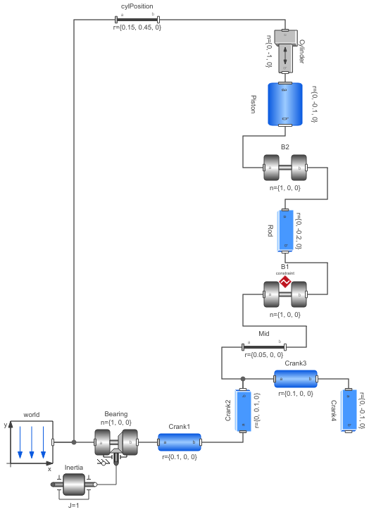
Diagram
Information
This information is part of the Modelica Standard Library maintained by the Modelica Association.
This is a model of the mechanical part of one cylinder of an engine. The combustion is not modelled. The "inertia" component at the lower left part is the output inertia of the engine driving the gearbox. The angular velocity of the output inertia has a start value of 10 rad/s in order to demonstrate the movement of the engine.
The engine is modeled solely by revolute and prismatic joints. Since this results in a planar loop there is the well known difficulty that the cut-forces perpendicular to the loop cannot be uniquely computed, as well as the cut-torques within the plane. This ambiguity is resolved by using the option planarCutJoint in the Advanced menu of one revolute joint in every planar loop (here: joint B1). This option sets the cut-force in direction of the axis of rotation, as well as the cut-torques perpendicular to the axis of rotation at this joint to zero and makes the problem mathematically well-formed.
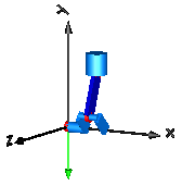
An animation of this example is shown in the figure below.
Components (14)
| Piston |
Type: BodyCylinder |
|
|---|---|---|
| Rod |
Type: BodyBox |
|
| B2 |
Type: Revolute |
|
| Bearing |
Type: Revolute |
|
| world |
Type: World |
|
| Inertia |
Type: Inertia |
|
| Crank4 |
Type: BodyBox |
|
| Crank1 |
Type: BodyCylinder |
|
| Crank3 |
Type: BodyCylinder |
|
| Crank2 |
Type: BodyBox |
|
| B1 | ||
| Mid |
Type: FixedTranslation |
|
| Cylinder |
Type: Prismatic |
|
| cylPosition |
Type: FixedTranslation |