FixedTranslationFixed translation of frame_b with respect to frame_a |
|
Information
This information is part of the Modelica Standard Library maintained by the Modelica Association.
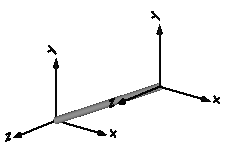
Component for a fixed translation of frame_b with respect to frame_a, i.e., the relationship between connectors frame_a and frame_b remains constant and frame_a is always parallel to frame_b.
By default, this component is visualized by a cylinder connecting frame_a and frame_b, as shown in the figure below. Note, that the two visualized frames are not part of the component animation and that the animation may be switched off via parameter animation = false.

Parameters (10)
| animation |
Value: true Type: Boolean Description: = true, if animation shall be enabled |
|---|---|
| r |
Value: Type: Position[3] (m) Description: Vector from frame_a to frame_b resolved in frame_a |
| shapeType |
Value: "cylinder" Type: ShapeType Description: Type of shape |
| r_shape |
Value: {0, 0, 0} Type: Position[3] (m) Description: Vector from frame_a to shape origin, resolved in frame_a |
| lengthDirection |
Value: to_unit1(r - r_shape) Type: Axis Description: Vector in length direction of shape, resolved in frame_a |
| widthDirection |
Value: {0, 1, 0} Type: Axis Description: Vector in width direction of shape, resolved in frame_a |
| length |
Value: Modelica.Math.Vectors.length(r - r_shape) Type: Length (m) Description: Length of shape |
| width |
Value: length / world.defaultWidthFraction Type: Distance (m) Description: Width of shape |
| height |
Value: width Type: Distance (m) Description: Height of shape |
| extra |
Value: 0.0 Type: ShapeExtra Description: Additional parameter depending on shapeType (see docu of Visualizers.Advanced.Shape) |
Inputs (2)
| color |
Default Value: Modelica.Mechanics.MultiBody.Types.Defaults.RodColor Type: Color Description: Color of shape |
|---|---|
| specularCoefficient |
Default Value: world.defaultSpecularCoefficient Type: SpecularCoefficient Description: Reflection of ambient light (= 0: light is completely absorbed) |
Connectors (2)
Components (2)
Used in Examples (23)
|
Modelica.Mechanics.MultiBody.Examples.Elementary Free flying body attached by two springs to environment |
|
|
Modelica.Mechanics.MultiBody.Examples.Elementary Demonstrate line force with two point masses using a JointUPS and alternatively a LineForceWithTwoMasses component |
|
|
Modelica.Mechanics.MultiBody.Examples.Elementary Simple spring/damper/mass system |
|
|
Modelica.Mechanics.MultiBody.Examples.Elementary Rigidly connected point masses in a point gravity field |
|
|
Modelica.Mechanics.MultiBody.Examples.Elementary Simple spring/damper/mass system |
|
|
Modelica.Mechanics.MultiBody.Examples.Elementary Mass attached with a spring to the world frame |
|
|
Modelica.Mechanics.MultiBody.Examples.Elementary 3-dim. springs in series and parallel connection |
|
|
Modelica.Mechanics.MultiBody.Examples.Elementary Rolling wheel set that is driven by torques driving the wheels |
|
|
Modelica.Mechanics.MultiBody.Examples.Elementary Rolling wheel set that is pulled by a force |
|
|
Modelica.Mechanics.MultiBody.Examples.Elementary Demonstrate the modeling of heat losses |
|
|
Modelica.Mechanics.MultiBody.Examples.Elementary Demonstrate the modeling of a user-defined gravity field |
|
|
Modelica.Mechanics.MultiBody.Examples.Elementary Demonstrate the visualization of a sine surface, as well as a torus and a wheel constructed from a surface |
|
|
Modelica.Mechanics.MultiBody.Examples.Loops Model of one cylinder engine |
|
|
Modelica.Mechanics.MultiBody.Examples.Loops Model of one cylinder engine with gas force and preparation for assembly joint JointRRP |
|
|
Modelica.Mechanics.MultiBody.Examples.Loops One kinematic loop with four bars (with only revolute joints; 5 non-linear equations) |
|
|
Modelica.Mechanics.MultiBody.Examples.Loops One kinematic loop with four bars (with UniversalSpherical joint; 1 non-linear equation) |
|
|
Modelica.Mechanics.MultiBody.Examples.Loops One kinematic loop with four bars (with JointSSP joint; analytic solution of non-linear algebraic loop) |
|
|
Modelica.Mechanics.MultiBody.Examples.Loops Mechanism with three planar kinematic loops and one degree-of-freedom with analytic loop handling (with JointRRR joints) |
|
|
Modelica.Mechanics.MultiBody.Examples.Rotational3DEffects Demonstrates that a cylindrical body can be replaced by Rotor1D model |
|
|
Modelica.Mechanics.MultiBody.Examples.Constraints Body attached by one spring and two prismatic joints or constrained to environment |
|
|
Modelica.Mechanics.MultiBody.Examples.Constraints Body attached by one spring and revolute joint or constrained to environment |
|
|
Modelica.Mechanics.MultiBody.Examples.Constraints Body attached by one spring and spherical joint or constrained to environment |
|
|
Modelica.Mechanics.MultiBody.Examples.Constraints Body attached by one spring and universal joint or constrained to environment |
Used in Components (13)
|
Modelica.Mechanics.MultiBody.Examples.Elementary.PointGravityWithPointMasses2 For comparison purposes, an equivalent model with Bodies instead of PointMasses |
|
|
Modelica.Mechanics.MultiBody.Examples.Loops.Utilities Cylinder with rod and crank of a combustion engine |
|
|
Modelica.Mechanics.MultiBody.Examples.Loops.Utilities One cylinder with analytic handling of kinematic loop |
|
|
Modelica.Mechanics.MultiBody.Examples.Loops.Utilities Model of one cylinder engine with gas force |
|
|
Modelica.Mechanics.MultiBody.Joints Ideal 3-dim. gearbox (arbitrary shaft directions) |
|
|
Modelica.Mechanics.MultiBody.Joints Joint (no mass, no inertia) that describes an ideal rolling wheel set (two ideal rolling wheels connected together by an axis) |
|
|
Modelica.Mechanics.MultiBody.Joints.Assemblies Universal - spherical - revolute joint aggregation (no constraints, no potential states) |
|
|
Modelica.Mechanics.MultiBody.Joints.Assemblies Universal - spherical - prismatic joint aggregation (no constraints, no potential states) |
|
|
Modelica.Mechanics.MultiBody.Joints.Assemblies Spherical - spherical - revolute joint aggregation with mass (no constraints, no potential states) |
|
|
Modelica.Mechanics.MultiBody.Joints.Assemblies Spherical - spherical - prismatic joint aggregation with mass (no constraints, no potential states) |
|
|
Modelica.Mechanics.MultiBody.Parts Rigid body with mass, inertia tensor, different shapes for animation, and two frame connectors (12 potential states) |
|
|
Modelica.Mechanics.MultiBody.Parts Rigid body with box shape. Mass and animation properties are computed from box data and density (12 potential states) |
|
|
Modelica.Mechanics.MultiBody.Parts Rigid body with cylinder shape. Mass and animation properties are computed from cylinder data and density (12 potential states) |