Library of sampler and hold blocks for Real signals
This package contains blocks that mark boundaries of a clocked partition
and transform a Real signal from one partition to the next. Especially,
the following blocks are provided:
| Boundary Type | Block Name | Description |
|---|---|---|
| continuous-time → clocked | Sample | Sample a continuous-time signal. |
| SampleClocked | Sample and associate a clock to the sampled scalar signal. | |
| SampleVectorizedAndClocked | Sample an input vector and associate a clock to the sampled vector signal. | |
| SampleWithADeffects | Sample with (simulated) Analog-Digital converter effects including noise. | |
| clocked → continuous-time | Hold | Hold a clocked signal with zero-order hold. |
| HoldWithDAeffects | Hold with (simulated) Digital-Analog converter effects and computational delay. | |
| clocked → clocked | SubSample | Sub-sample a signal (output clock is slower as input clock). |
| SuperSample | Super-sample a signal (output clock is faster as input clock). | |
| SuperSampleInterpolated | Super-sample a signal with linear interpolation (output clock is faster as input clock). | |
| ShiftSample | Shift a signal (output clock is delayed with respect to input clock). | |
| BackSample | Shift a signal and start the output clock before the input clock with a start value. | |
| within clocked partition | AssignClock | Assign a clock to a clocked scalar signal. |
| AssignClockVectorized | Assign a clock to a clocked vector signal. |
Additionally, package Utilities contains utility blocks that are used as building blocks for user-relevant blocks. Especially, block UpSample can be used in combination with a FIR filter block to model super-sampling with interpolation and filtering.
Extends from Modelica.Icons.Package (Icon for standard packages).
| Name | Description |
|---|---|
| Sample the continuous-time, Real input signal and provide it as clocked output signal (clock is inferred) | |
| Sample the continuous-time, Real input signal and provide it as clocked output signal. The clock is provided as input signal | |
| Sample the continuous-time, Real input signal vector and provide it as clocked output signal vector. The clock is provided as input signal | |
| Sample with (simulated) Analog-Digital converter effects including noise | |
| Hold the clocked, Real input signal and provide it as continuous-time output signal (zero order hold) | |
| Hold with (simulated) Digital-Analog converter effects and computational delay | |
| Sub-sample the clocked Real input signal and provide it as clocked output signal | |
| Super-sample the clocked Real input signal and provide it as clocked output signal | |
| Super-sample the clocked Real input signal and provide it linearly interpolated as clocked output signal (this is also called an Interpolator) | |
| Shift the clocked Real input signal by a fraction of the last interval and and provide it as clocked output signal | |
| Shift the clock of the Real input signal backwards in time (and access the most recent value of the input at this new clock) | |
| Assign a clock to a clocked Real signal | |
| Assign a clock to a clocked Real signal vector | |
| Utility components that are usually not directly used |
 Modelica.Clocked.RealSignals.Sampler.Sample
Sample the continuous-time, Real input signal and provide it as clocked output signal (clock is inferred)
This block samples the continuous-time, Real input signal u and provides it as clocked output signal y. The clock of the output signal is inferred (that is, it needs to be defined somewhere else in the clocked partition). If this is not desired, use block SampleClocked instead, to explicitly assign a clock to the output signal.
To be more precise: The input signal u(t) must be a continuous-time signal.
The output signal y(ti) is associated to a clock (defined somewhere else).
At a clock tick, the left limit of u is assigned to y:
y(ti) = u(ti-eps) (= the value of u just before the clock
became active). Since the operator returns the left limit of u, it introduces an
infinitesimal small delay between the continuous-time and the clocked partition.
This corresponds to the reality, where a sampled data system cannot act infinitely
fast and even for a very idealized simulation, an infinitesimal small delay is present.
As a result, algebraic loops between clocked and continuous-time partitions cannot
occur.
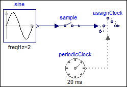
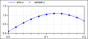
The following
example
samples a sine signal with a periodic clock of 20 ms period:
 |
 |
|
| model | simulation result |
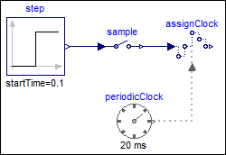
In the following
example
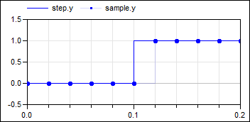
the continuous-time input signal contains a discontinuous value change at the 0.1 s
clock tick. It can be seen that the Sample block samples the left limit of the
step signal:
 |
 |
|
| model | simulation result |
In the following
example
a direct feedthrough in the continuous-time and in the clocked partition is present.
Without a time-delay, this would result in an algebraic loop. However, since block
Sample samples the left limit of a continuous-time signal, sampling introduces a
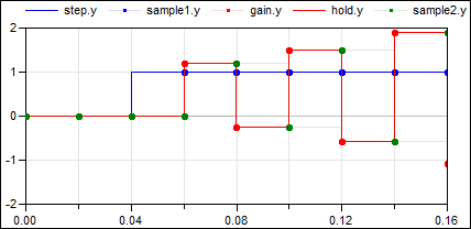
delay of one sample period that breaks the algebraic loop:
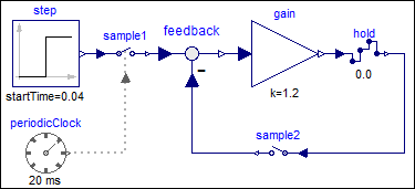 |
|
| model |
|
 |
|
| simulation result |
Note, the reason for the delay is that sample2.y (= the green, clocked signal) is the left limit of hold.y (= the red, continuous-time signal).
Extends from Clocked.RealSignals.Interfaces.PartialSISOSampler (Basic block used for sampling of Real signals).
| Name | Description |
|---|---|
| u | Connector of continuous-time, Real input signal |
| y | Connector of clocked, Real output signal |
 Modelica.Clocked.RealSignals.Sampler.SampleClocked
Sample the continuous-time, Real input signal and provide it as clocked output signal. The clock is provided as input signal
This block is similar to the Sample block. The only difference is that a clock signal is provided via a second input and the output is associated to this clock.
Note, it does not make much sense to vectorize this block, because then also the clock input is vectorized. Instead, if the input signal is a vector, use block SampleVectorizedAndClocked that has a vector Real input and output, as well as a scalar clock input.
The following
example
samples a sine signal with a periodic clock of 20 ms period:
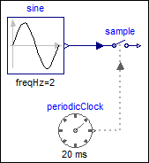 |
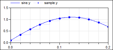 |
|
| model | simulation result |
Extends from Clocked.RealSignals.Interfaces.SamplerIcon (Basic graphical layout of block used for sampling of Real signals).
| Name | Description |
|---|---|
| u | Connector of continuous-time, Real input signal |
| y | Connector of clocked, Real output signal |
| clock | Output signal y is associated with this clock input |
 Modelica.Clocked.RealSignals.Sampler.SampleVectorizedAndClocked
Sample the continuous-time, Real input signal vector and provide it as clocked output signal vector. The clock is provided as input signal
This block is similar to the SampleClocked block. The only difference is that the continuous-time input signal is a vector: All input signals are sampled and are associated with the scalar clock signal provided via the second input.
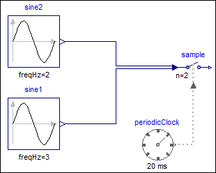
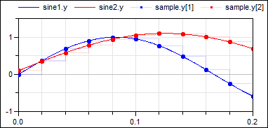
The following
example
has a vector as input, consisting of two different sine signals. These
signals are sampled with a periodic clock of 20 ms period:
 |
 |
|
| model | simulation result |
Extends from Clocked.RealSignals.Interfaces.SamplerIcon (Basic graphical layout of block used for sampling of Real signals).
| Name | Description |
|---|---|
| n | Size of input signal vector u (= size of output signal vector y) |
| Name | Description |
|---|---|
| u[n] | Connector of continuous-time, Real input signal vector |
| y[n] | Connector of clocked, Real output signal vector |
| clock | Output signal vector y is associated with this clock input |
 Modelica.Clocked.RealSignals.Sampler.SampleWithADeffects
Sample with (simulated) Analog-Digital converter effects including noise
This block is similar to the Sample block. The only difference is that after the sampling of the input signal, simulated real-world effects are applied on the sampled signal. In particular:
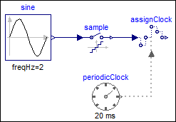
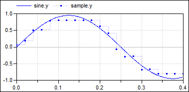
The following example samples a sine signal with a periodic clock of 20 ms period, and adds the following effects:
 |
 |
|
| model | simulation result |
The output y is quite far away from the continuous-time input signal,
due to the strong discretization and large noise applied to the
sampled input.
Extends from Clocked.RealSignals.Interfaces.PartialSISOSampler (Basic block used for sampling of Real signals).
| Name | Description |
|---|---|
| Sampling and noise | |
| noisy | = true, if output should be superimposed with noise |
| noise | Noise model |
| Limiting and quantization | |
| limited | = true, if output is limited |
| quantized | = true, if output quantization effects included |
| yMax | Upper limit of output (if limited = true) |
| yMin | Lower limit of output (if limited = true) |
| bits | Number of bits of quantization (if quantized = true) |
| Name | Description |
|---|---|
| u | Connector of continuous-time, Real input signal |
| y | Connector of clocked, Real output signal |
 Modelica.Clocked.RealSignals.Sampler.Hold
Hold the clocked, Real input signal and provide it as continuous-time output signal (zero order hold)
This block holds the clocked Real input signal u with a zero order hold and provides it as continuous-time output signal y. The clock of the input signal is inferred (that is, it needs to be defined somewhere else in the clocked partition).
To be more precise: The input signal u(ti) must be a clocked signal. The output signal y(t) is a piecewise constant continuous-time signal. When the clock of u ticks at time ti, the block output y(ti) = u(ti). Otherwise y(t), t ≥ti, is the value of u(ti) from the last clock activation at time ti. Before the first clock activation of u, the block outputs the value of parameter y_start. The value of this parameter is displayed below the icon.
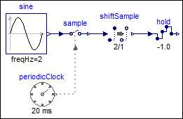
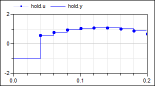
The following
example
samples a sine signal with a periodic clock of 20 ms period and delays it for 2 sample periods.
The resulting signal is hold with the Hold block. As a result, the clock of hold.u starts
ticking at 40 ms. The output hold.y of the block is a continuous-time signal that is present
from the start of the simulation. Before the first tick of the clock of hold.u, it is set
to -1.0 (= the value of parameter hold.y_start).
 |
 |
|
| model | simulation result |
Extends from Clocked.RealSignals.Interfaces.PartialSISOHold (Basic block used for zero order hold of Real signals).
| Name | Description |
|---|---|
| y_start | Value of output y before the first tick of the clock associated to input u |
| Name | Description |
|---|---|
| u | Connector of clocked, Real input signal |
| y | Connector of continuous-time, Real output signal |
 Modelica.Clocked.RealSignals.Sampler.HoldWithDAeffects
Hold with (simulated) Digital-Analog converter effects and computational delay
This block is similar to the Hold block. The only difference is that simulated real-world effects are applied on the clocked input signal u before transforming the signal to a continuous-time signal with a zero-order hold. In particular:
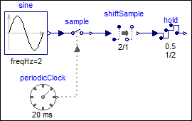
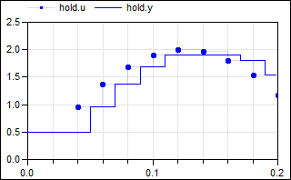
The following example samples a sine signal with an amplitude of 2.0 with a periodic clock of 20 ms period and delays it for 2 sample periods. The resulting signal is hold with the HoldWithDAeffects block. As a result, the clock of hold.u starts ticking at 40 ms. The output hold.y of the block is a continuous-time signal that is present from the start of the simulation. Before the first tick of the clock of hold.u, it is set to 0.5 (= the value of parameter hold.y_start). Additionally, the following effects are added to the hold block:
 |
 |
|
| model | simulation result |
Due to the limitation of the output signal, the values of hold.u ≥ 1.9
are limited to 1.9.
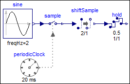
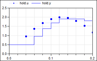
If the hold output is delayed by one sample period, then the previous(…) value of the
input is output, and the first tick is delayed by one sample period,
as shown by the
modified example
from above:
 |
 |
|
| model | simulation result |
Note, the computational delay of one sample period is defined
by shiftCounter=1, resolution=1, as shown in the icon of the
hold block.
Extends from Clocked.RealSignals.Interfaces.PartialSISOHold (Basic block used for zero order hold of Real signals).
| Name | Description |
|---|---|
| y_start | Value of output y before the first tick of the clock associated to input u |
| Computational delay in seconds = interval() * shiftCounter/resolution | |
| computationalDelay | =true, if a computational delay should be imposed |
| shiftCounter | (min=0, max=resolution), computational delay = interval()*shiftCounter/resolution |
| resolution | Time quantization resolution of sample interval |
| Limiting and quantization | |
| limited | = true, if output is limited |
| quantized | = true, if output quantization effects included |
| yMax | Upper limit of output (if limited = true) |
| yMin | Lower limit of output (if limited = true) |
| bits | Number of bits of quantization (if quantized = true) |
| Name | Description |
|---|---|
| u | Connector of clocked, Real input signal |
| y | Connector of continuous-time, Real output signal |
 Modelica.Clocked.RealSignals.Sampler.SubSample
Sub-sample the clocked Real input signal and provide it as clocked output signal
This block sub-samples the clocked Real input signal u and provides it as clocked output signal y.
To be more precise: The clock of y is factor-times slower than the clock of u. At every factor ticks of the clock of u, the output y returns the value of u. The first activation of the clock of y coincides with the first activation of the clock of u. By default, the sub-sampling factor is inferred, that is, it must be defined somewhere else. If parameter inferFactor = false, then the sub-sampling factor is defined by Integer parameter factor.
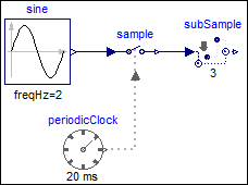
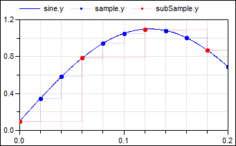
The following
example
samples a sine signal with a periodic clock of 20 ms period, and
then sub-samples the resulting clocked signal with a factor of 3:
 |
 |
|
| model | simulation result |
As can be seen, subSample.y picks every third-value of sample.y due to the sub-sampling, and the sub-sampling factor = 3 is displayed in the icon of the subSample block. Note the down-arrow in the icon of the subSample block indicates that the clock of subSample.y is slower as the clock of subSample.u.
| Name | Description |
|---|---|
| inferFactor | = true, if sub-sampling factor is inferred |
| factor | Sub-sampling factor >= 1 (ignored if inferFactor=true) |
| Name | Description |
|---|---|
| u | Connector of clocked, Real input signal |
| y | Connector of clocked, Real output signal (clock of y is slower as clock of u) |
 Modelica.Clocked.RealSignals.Sampler.SuperSample
Super-sample the clocked Real input signal and provide it as clocked output signal
This block super-samples the clocked Real input signal u and provides it as clocked output signal y.
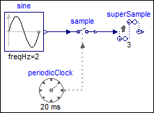
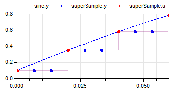
To be more precise: The clock of y is factor-times faster than the clock of u. At every tick of the clock of y, the value of y is set to the value of u from the last tick of the clock of u. The first activation of the clock of y coincides with the first activation of the clock of u. By default, the super-sampling factor is inferred, that is, it must be defined somewhere else. If parameter inferFactor = false, then the super-sampling factor is defined by Integer parameter factor.
For control applications this block introduces unnecessary "vibrations". In such a case it is better to use block SuperSampleInterpolated instead.
The following
example
samples a sine signal with a periodic clock of 20 ms period, and
then super-samples the resulting clocked signal with a factor of 3:
 |
 |
|
| model | simulation result |
As can be seen, superSample introduces factor-1 additional clock ticks for the output y. The super-sampling factor = 3 is displayed in the icon of the superSample block. Note the up-arrow in the icon of the superSample block indicates that the clock of superSample.y is faster as the clock of superSample.u.
| Name | Description |
|---|---|
| inferFactor | = true, if super-sampling factor is inferred |
| factor | Super-sampling factor >= 1 (ignored if inferFactor=true) |
| Name | Description |
|---|---|
| u | Connector of clocked, Real input signal |
| y | Connector of clocked, Real output signal (clock of y is faster as clock of u) |
 Modelica.Clocked.RealSignals.Sampler.SuperSampleInterpolated
Super-sample the clocked Real input signal and provide it linearly interpolated as clocked output signal (this is also called an Interpolator)
This block super-samples the clocked Real input signal u and provides it linearly interpolated between the u-values as clocked output signal y.
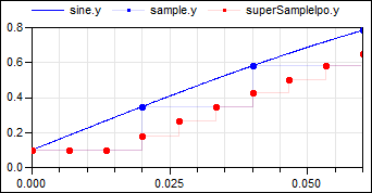
To be more precise: The clock of y is factor-times faster than the clock of u. At every tick of the clock of y, the value of y is set to the value of the linearly interpolated value between the last available values of u. The first activation of the clock of y coincides with the first activation of the clock of u. By default, the super-sampling factor is inferred, that is, it must be defined somewhere else. If parameter inferFactor = false, then the super-sampling factor is defined by Integer parameter factor.
For control applications, this block is better suited as block SuperSample since it does not induce "vibrations".
The following
example
samples a sine signal with a periodic clock of 20 ms period, and
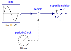
then super-samples the resulting clocked signal with a factor of 3
and interpolates the result linearly:
 |
 |
|
| model | simulation result |
As can be seen, block superSampleIpo introduces 3 additional clock ticks for the output y and determines the values at these clock ticks, so that the last two available values of the input u are linearly interpolated. The super-sampling factor = 3 is displayed in the icon of the superSampleIpo block. Note the up-arrow in the icon of the SuperSampleInterpolation block indicates that the clock of superSampleIpo.y is faster as the clock of superSampleIpo.u.
| Name | Description |
|---|---|
| inferFactor | = true, if super-sampling factor is inferred |
| factor | Super-sampling factor >= 1 (if inferFactor=false) |
| Name | Description |
|---|---|
| u | Connector of clocked, Real input signal |
| y | Connector of clocked, Real output signal |
 Modelica.Clocked.RealSignals.Sampler.ShiftSample
Shift the clocked Real input signal by a fraction of the last interval and and provide it as clocked output signal
This block shifts the first activation of the clock of the output y by fraction shiftCounter/resolution of the period (or for a non-periodic signal by a fraction of the last interval) and the output y is set to the last available value of the input u. Here, shiftCounter and resolution are positive Integer parameters.
To be more precise: The block constructs (conceptually) a clock “cBase”
Clock cBase = subSample(superSample(u, resolution), shiftCounter)
and the clock of y starts at the second clock tick of cBase. At every tick of the clock of y, the operator returns the value of u from the last tick of the clock of u.
Note, for EventClocks there is the restriction that block ShiftSample can only shift the number of ticks of the EventClock clock, but cannot introduce new ticks, due to the restriction of operator superSample on EventClocks.
Also note, that this block does not simply shift the signal in time, since only the value of u from the last tick of the clock of u is used for the output. If a time-delayed clock is desired, use instead block NonPeriodic.FractionalDelay where the input signal is delayed by a time period and old values of u are stored in a buffer. If the time delay is less than one period, the two blocks, ShiftSample and FractionalDelay, give the same result.
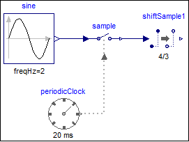
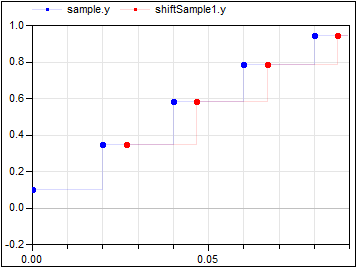
The following
example
samples a sine signal with a periodic clock of 20 ms period, and
then shifts it with shiftCounter = 4 and resolution = 3:
 |
 |
|
| model | simulation result |
The first activation of output y of block shiftSample1 is shifted in time (4/3*20ms). The parameter values shiftCounter = 4 and resolution = 3 are visible at the bottom of the icon. Also note, that the signal is not simply a shift in time. The output of a ShiftSample block will always be the value from the last tick of the clock of its inputs.
| Name | Description |
|---|---|
| Shift first clock activation for 'shiftCounter/resolution*interval(u)' seconds | |
| shiftCounter | Numerator of shifting formula |
| resolution | Denominator of shifting formula |
| Name | Description |
|---|---|
| u | Connector of clocked, Real input signal |
| y | Connector of clocked, Real output signal |
 Modelica.Clocked.RealSignals.Sampler.BackSample
Shift the clock of the Real input signal backwards in time (and access the most recent value of the input at this new clock)
This block shifts the first activation of the clock of the output y by fraction backCounter/resolution of the period (or for a non-periodic signal by a fraction of the last interval) before the first activation of the clock of u. The output y is set to the last available value of the input u. Here, backCounter and resolution are positive Integer parameters.
To be more precise: The block constructs (conceptually) a clock “cBase”
Clock cBase = subSample(superSample(u, resolution), backCounter)
and the first clock tick of y is shifted before the first tick of the clock of u, such that this duration is identical to the duration between the first and second clock tick of cBase. Before the first tick of the clock of u, the block outputs the value of parameter y_start. After that, the block returns the last available value of u.
Note, for EventClocks there is the restriction that block BackSample can only shift the number of ticks of the EventClock clock, but cannot introduce new ticks, due to the restriction of operator superSample on EventClocks.
Also note, that this block does not simply shift the signal in time, since only the value of u from the last tick of the clock of u is used for the output. In particular, a BackSample block following a ShiftSample block cannot be used to recover the input signal of ShiftSample (for a causal system this is impossible).
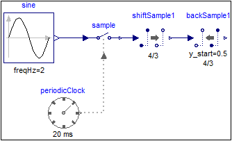
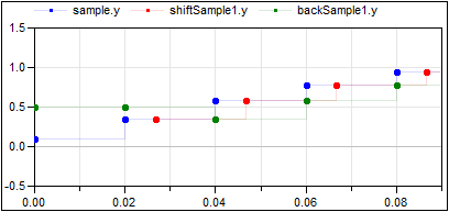
The following
example
samples a sine signal with a periodic clock of 20 ms period,
shift-samples it with shiftCounter = 4 and resolution = 3 and then back-samples it with backCounter=4 and resolution = 3:
 |
 |
|
| model | simulation result |
The first activation of output y of block backSample1 is shifted (4/3*20ms) before the first activation of output y of block shiftSample1. As a consequence, the activation times of the output y are coincident with the input signal of the shiftSample1 block. However, as described above, the output of block backSample1 does not recover the original sampled sine signal! For the first two ticks the output holds the value of the parameter y_start = 0.5. After that the output at a clock tick of block backSample1 is the last value of the output of the shiftSample1 block. The parameter values y_start = 0.5, shiftCounter = 4 and resolution = 3 are visible at the bottom of the icon.
| Name | Description |
|---|---|
| y_start | Value of output y before the first clock tick of the input u |
| Shift first clock activation backwards in time for 'shiftCounter/resolution*interval(u)' seconds | |
| backCounter | Numerator of shifting formula |
| resolution | Denominator of shifting formula |
| Name | Description |
|---|---|
| u | Connector of clocked, Real input signal |
| y | Connector of clocked, Real output signal (clock of y is faster than clock of u) |
 Modelica.Clocked.RealSignals.Sampler.AssignClock
Assign a clock to a clocked Real signal
This block assigns a clock to the Real input signal u and provides u as output signal y.
The following
example
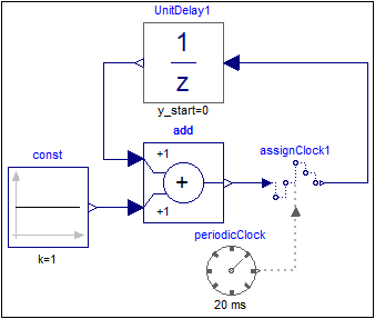
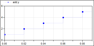
shows a discrete counter. In order to execute the counter with a sample period of 20ms an AssignClock block is used. Due to clock inference all equations within the blocks are deduced to be active at the clock ticks given by the periodicClock block.
 |
 |
|
| model | simulation result |
At every clock tick (that is at every 20ms) the output of the unitDelay1 block is incremented by one.
| Name | Description |
|---|---|
| u | Connector of clocked, Real input signal |
| y | Connector of clocked, Real output signal |
| clock |
 Modelica.Clocked.RealSignals.Sampler.AssignClockVectorized
Assign a clock to a clocked Real signal vector
This block assigns a clock to the Real vector input signal u and provides u as vector output signal y.
The following
example
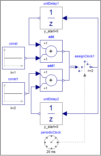
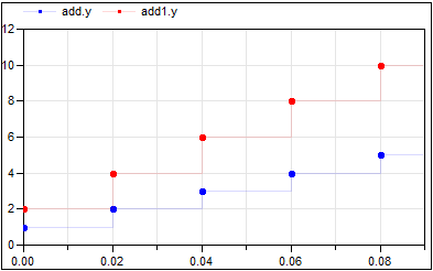
shows two discrete counters. In order to execute the counters with a sample period of 20ms an AssignClockVectorized block is used. Due to clock inference all equations within the blocks are deduced to be active at the clock ticks given by the periodicClock block.
 |
 |
|
| model | simulation result |
At every clock tick (that is every 20ms) the output of the unitDelay1 block is incremented by one and that of the unitDelay2 block is incremented by two. The vector size of the input and output is provided by parameter n=2 which is also shown in the icon of block assignClock1.
| Name | Description |
|---|---|
| n | Size of input signal vector u (= size of output signal vector y) |
| Name | Description |
|---|---|
| u[n] | Connector of clocked, Real input signal |
| y[n] | Connector of clocked, Real output signal |
| clock |