Utility components that are usually not directly used
This package contains utility blocks that are usually not directly utilized but are used as building blocks for "higher level" blocks.
Extends from Modelica.Icons.UtilitiesPackage (Icon for utility packages).
| Name | Description |
|---|---|
| Upsample the clocked Real input signal and provide it as clocked output signal | |
| Generate a Boolean continuous-time trigger signal from a clocked Real input | |
| Generate a Boolean continuous-time square-wave output from a clocked Real input | |
| Internal blocks and functions that are usually of no interest for the user |
 Modelica.Clocked.RealSignals.Sampler.Utilities.UpSample
Upsample the clocked Real input signal and provide it as clocked output signal
This block upsamples the clocked Real input signal u and provides it as clocked output signal y.
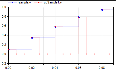
To be more precise: The clock of y is factor-times faster than the clock of u. At every tick of the clock of u, the value of y is set to the value of u, at intermediate ticks of clock y, the value of y is set to zero. The first activation of the clock of y coincides with the first activation of the clock of u. By default, the upsampling factor is inferred,that is, it must be defined somewhere else. If parameter inferFactor = false, then the upsampling factor is defined by the Integer parameter factor.
For signal interpolation an upsample should be followed by an appropriate filter (anti-imaging).
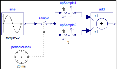
The following
example
samples a sine signal with a periodic clock of 20 ms period, and
then upsamples the resulting clocked signal with a factor of 3:
 |
 |
|
| model | simulation result |
The upsampling factor is explicitly given at the upSample2 block, which also makes the factor visible in the icon. For the upSample1 block the factor is inferred. As can be seen, upsample1 introduces 3 additional clock ticks for the output y. Note, the up-arrow in the icon of the upSample blocks indicates that the clocks of their outputs is faster than the clocks of their inputs.
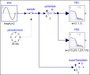
The following
example
samples a sine signal with a periodic clock of 20 ms period,
upsamples the resulting clocked signal with a factor of 3
and applies varies filters on this signal:
 |
|
| model |
|
 |
|
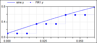
| simulation result 1 |
|
 |
|
| simulation result 2 |
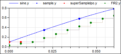
This model shows various possibilities to operate on an up-sampled signal: When filtering the upsampled signal with filter block FIR1 using FIR coefficients {1,1,1}, then the result is identical to a super-sampled signal (see signal FIR1.y in figure "simulation result 1"). On the other hand, when filtering the upsampled signal with filter block FIR2 using FIR coefficients {1/3, 2/3, 1, 2/3, 1/3}, then the result is a linearly interpolated super-sampled signal (see signal FIR2.y in figure "simulation result 2"). The same result can be achieved with block SuperSampleInterpolated (see signal superSampleIpo1.y in figure "simulation result 2"). The only difference are the first clock ticks, since the FIR2 signal is initialized a bit differently.
| Name | Description |
|---|---|
| inferFactor | = true, if upsampling factor is inferred |
| factor | Upsampling factor >= 1 (if inferFactor=false) |
| Name | Description |
|---|---|
| u | Connector of clocked, Real input signal |
| y | Connector of clocked, Real output signal (clock of y is faster as clock of u) |
 Modelica.Clocked.RealSignals.Sampler.Utilities.AssignClockToTriggerHold
Generate a Boolean continuous-time trigger signal from a clocked Real input
This block creates a Boolean, continuous time, trigger signal whenever the clock of the input signal is active.
A particular use-case in which that block might be useful is the combination of "old-style" sampled blocks (i.e., "unclocked" discrete control functions implemented using equations between "when trigger then" clauses) with clocked blocks.
The following
example
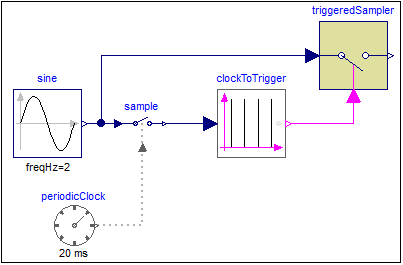
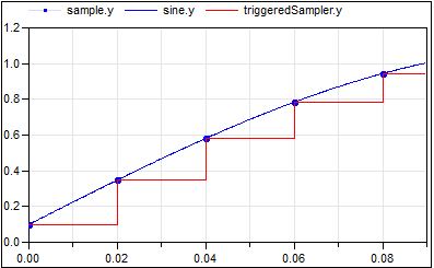
samples a sine signal with a periodic clock of 20 ms period. After that a continuous time Boolean trigger signal is generated at every clock tick of that sampled signal. The generated signal is used as trigger signal for an "old-style" TriggeredSampler block from the Modelica.Blocks.Discrete package:
 |
 |
|
| model | simulation result |
Note, that it is clearly visible in the plot that the "old-style" discrete variables have an implicit zero-order hold semantics, while the new clocked variables are only active whenever their associated clock ticks. Just compare variable sample.y (clocked) with triggeredSampler.y (unclocked) to observe the difference.
Extends from Clocked.ClockSignals.Interfaces.ClockedBlockIcon (Basic graphical layout of block where at least one input or output is a clocked variable).
| Name | Description |
|---|---|
| y_start | Initial value of output signal |
| Name | Description |
|---|---|
| u | |
| y | Connector of Boolean output signal |
 Modelica.Clocked.RealSignals.Sampler.Utilities.AssignClockToSquareWaveHold
Generate a Boolean continuous-time square-wave output from a clocked Real input
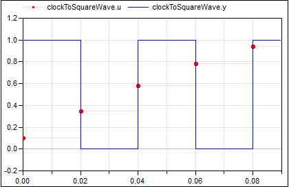
This block creates a Boolean, continuous time, square-wave output. Whenever the clock of the input signal is active the Boolean output value changes.
The following
example
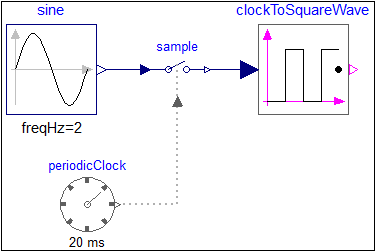
samples a sine signal with a periodic clock of 20 ms period. After that a Boolean, continuous time, square-wave signal is generated that changes its value at every clock tick of the sampled signal:
 |
 |
|
| model | simulation result |
Extends from Clocked.ClockSignals.Interfaces.ClockedBlockIcon (Basic graphical layout of block where at least one input or output is a clocked variable).
| Name | Description |
|---|---|
| y_start | Initial value of output signal |
| Name | Description |
|---|---|
| u | |
| y | Connector of Boolean output signal |