CauerLowPassAnalogCauer low pass filter with analog components |
|
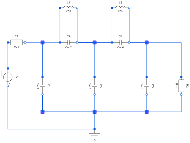
Diagram
Information
This information is part of the Modelica Standard Library maintained by the Modelica Association.
The example Cauer Filter is a low-pass-filter of the fifth order. It is realized using an analog network. The voltage source V is the input voltage (step), and the R2.p.v is the filter output voltage. The pulse response is calculated.
The simulation end time should be 60. Please plot both V.p.v (input voltage) and R2.p.v (output voltage).
Parameters (7)
| l1 |
Value: 1.304 Type: Inductance (H) Description: filter coefficient I1 |
|---|---|
| l2 |
Value: 0.8586 Type: Inductance (H) Description: filter coefficient I2 |
| c1 |
Value: 1.072 Type: Capacitance (F) Description: filter coefficient c1 |
| c2 |
Value: 1 / (1.704992 ^ 2 * l1) Type: Capacitance (F) Description: filter coefficient c2 |
| c3 |
Value: 1.682 Type: Capacitance (F) Description: filter coefficient c3 |
| c4 |
Value: 1 / (1.179945 ^ 2 * l2) Type: Capacitance (F) Description: filter coefficient c4 |
| c5 |
Value: 0.7262 Type: Capacitance (F) Description: filter coefficient c5 |