ThyristorCenterTapmPulse_RLV_CharacteristicCharacteristic of 2*m pulse thyristor rectifier with center tap and R-L load and voltage |
|
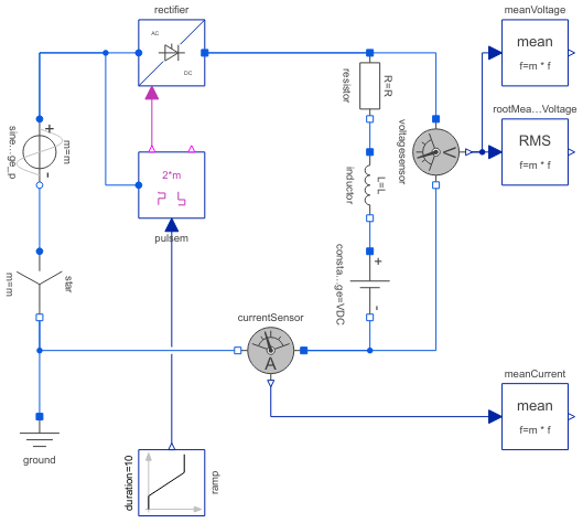
Diagram
Information
This information is part of the Modelica Standard Library maintained by the Modelica Association.
This example shows a controlled m pulse center tap rectifier with R-L load including DC voltage source, where m is the number of phases. The additional DC voltage source in this example enables negative average load voltages.
Plot average voltage meanVoltage.v versus firingAngle pulsem.firingAngle to see control characteristic of this type of rectifier with R-L load including active voltage.
Parameters (5)
| Vrms |
Value: 110 Type: Voltage (V) Description: RMS supply voltage |
|---|---|
| f |
Value: 50 Type: Frequency (Hz) Description: Frequency |
| R |
Value: 20 Type: Resistance (Ω) Description: Load resistance |
| L |
Value: 1 Type: Inductance (H) Description: Load resistance |
| VDC |
Value: -50 Type: Voltage (V) Description: DC load offset voltage |
Components (14)
| ground |
Type: Ground |
|
|---|---|---|
| star |
Type: Star |
|
| sineVoltage_p |
Type: SineVoltage |
|
| rectifier |
Type: ThyristorCenterTapmPulse |
|
| voltagesensor |
Type: VoltageSensor |
|
| meanVoltage |
Type: Mean |
|
| rootMeanSquareVoltage |
Type: RootMeanSquare |
|
| currentSensor |
Type: CurrentSensor |
|
| meanCurrent |
Type: Mean |
|
| pulsem |
Type: VoltageBridge2mPulse |
|
| resistor |
Type: Resistor |
|
| inductor |
Type: Inductor |
|
| constantVoltage |
Type: ConstantVoltage |
|
| ramp |
Type: Ramp |