CoupledClutchesDrive train with 3 dynamically coupled clutches |
|
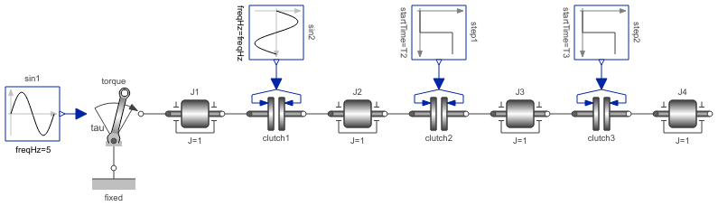
Diagram
Information
This information is part of the Modelica Standard Library maintained by the Modelica Association.
This example demonstrates how variable structure drive trains are handled. The drive train consists of 4 inertias and 3 clutches, where the clutches are controlled by input signals. The system has 2^3=8 different configurations and 3^3 = 27 different states (every clutch may be in forward sliding, backward sliding or locked mode when the relative angular velocity is zero). By invoking the clutches at different time instances, the switching of the configurations can be studied.
Simulate the system for 1.2 seconds with the
following initial values:
J1.w = 10.
Plot the following variables:
angular velocities of inertias (J1.w, J2.w, J3.w,
J4.w), frictional torques of clutches (clutchX.tau),
frictional mode of clutches (clutchX.mode) where
mode = -1/0/+1 means backward sliding,
locked, forward sliding.